DAC Basic Configurations 3 (Thermometer Code Method)
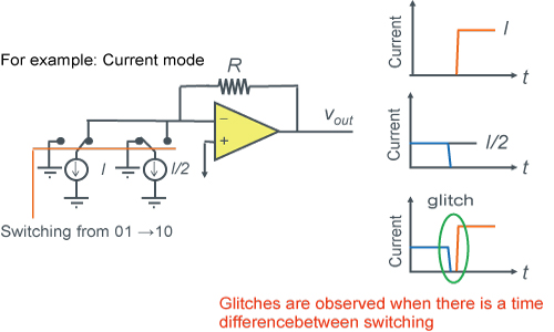
At the moment data is switched there may be a very different output voltage, possibly causing noise to be generated at the output analog signal. This noise can be referred to as a glitch. As one workaround for these types of glitches, the thermometer code method is often used.

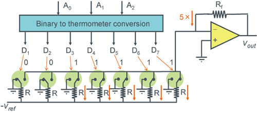
Thermometer codes are the representation of numbers based on how many '1s' are present. However, although glitches can be reduced, the size of decoders for binary to thermometer code can increase in scale exponentially based on resolution.

Thermometer Code (Resistance Mode) D/A Converter Example
3bit DAC using thermometer codes.
Natural glitches do not occur.

Thermometer Code (Current Mode) D/A Converter Example
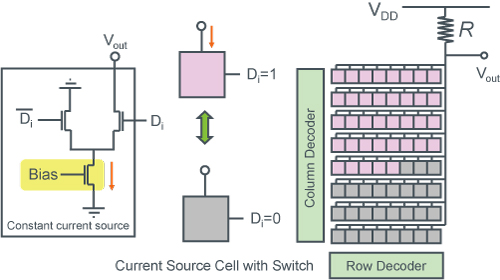
A current mode D/A Converter determines the output voltage Vo by pulling current from a number of cells.
The figure below shows an 8x8 configuration (64 gradation) = 6bit resolution
By simply increasing the pink section, current pulled from R rises, reducing Vout.
Thermometer code control prevents glitches from occurring at Vout.

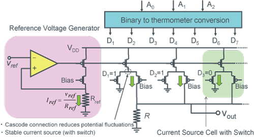
In the above diagram of a current type D/A converter, up and down are reversed.
Cascode current sources are less affected by output voltage, achieving high accuracy.
As a result, the output voltage range is reduced.


