Schottky Barrier Diodes (SBD)
Understanding the Schottky Barrier Diode
| Structure | Symbol | Applications・Characteristics |
|---|---|---|
 |
 |
|
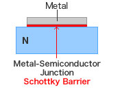
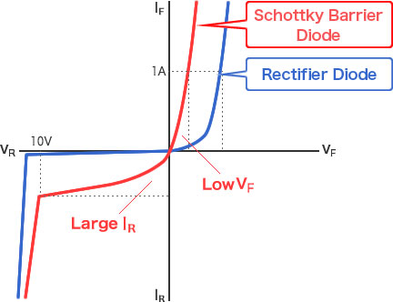
Unlike conventional diodes that provide diode characteristics through a PN (semiconductor-semiconductor) junction, Schottky barrier diodes utilize a metal-semiconductor junction. This results in much lower VF characteristics (forward voltage drop) compared with PN junction diodes, enabling faster switching speeds. However, one drawback is larger leakage current (IR), making countermeasures necessary to prevent thermal runaway.
The low forward voltage of Schottky diodes contributes to energy efficiency, making them ideal for power supplies and photovoltaic systems.

SBDs, which are often used for secondary power supply rectification, feature characteristics that can vary greatly depending on the type of metal used. Schottky diode construction involves a metal electrode bonded to an N-type semiconductor. ROHM offers a lineup of SBDs that utilize a variety of different metals.
- RB**1 series low VF type
- RB**0 series low IR type
- ROHM offers the RB**8 series of ultra-low-IR diodes for automotive application
Key Points on Schottky Barrier Diode
- Low VF and IR types can be achieved by simply changing the type of metal.
- Low forward voltage drop: Schottky diodes are known for their low forward voltage drop, which minimizes energy loss as heat. This characteristic enhances energy efficiency and performance, making them ideal for applications such as photovoltaic systems and rapid switching in electronic circuits.
Thermal Runaway in Schottky Diodes
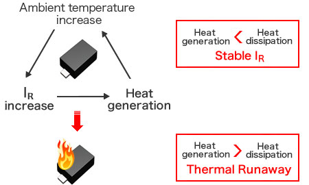
Schottky barrier diodes are susceptible to excessive heat generation during large current flow. As a result, the combination of high heat with increasing IR (leakage current) can cause both the case and ambient temperature to rise. Consequently, implementing incorrect thermal design may result in the amount of heat generated to exceed the amount dissipated, which can lead to increasing heat generation and leakage current and eventually result in damage. This phenomenon is referred to as “thermal runaway.”

Key Points
- High ambient temperatures can cause thermal runaway


