Precautions When Using Chip Resistors
Factors that Affect TCR ①
Factor ① Position of Sensing Lines
Shunt resistors typically have low resistance values ranging from the tens of μΩ to hundreds of mΩ.
To measure the voltage at such low resistances, a 4-wire Kelvin connection is utilized.
However, if the sensing lines are laid out outside the shunt resistor pads as shown in Fig. 1, accurate measurement is not possible as the resistance components of the copper foil wiring and solder must be included.
What’s more, the TCR of the copper foil wiring is around 3900ppm/K, which is significantly larger than the inherent value of the shunt resistor.
To reduce the effects of the copper foil with respect to TCR, the sensing lines must be laid out within the shunt resistor pads as shown in Figs. 2-4.
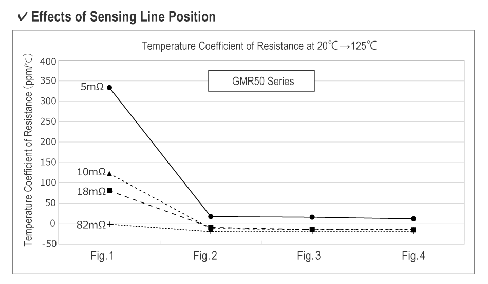
A comparison of the TCR (20℃→125℃) for each respective sensing line position at different resistance values of the GMR50 series is shown below.
Figs. 2-4 do not exhibit a large difference, while Fig. 1 shows a significantly higher TCR.
TCR values indicated in ROHM datasheets are based on measurements taken on a board with sensing lines generally laid out in the center of the pads (Fig. 4).
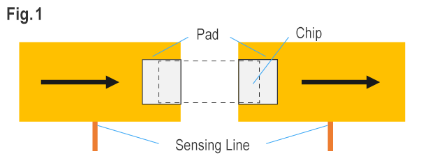
・Sensing lines laid out on the outside of the pads
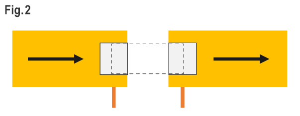
・Sensing lines laid out on the bottom center of the pads
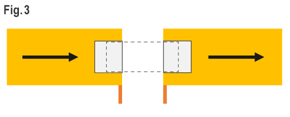
・Sensing lines laid out on the lower inside edge of the pads
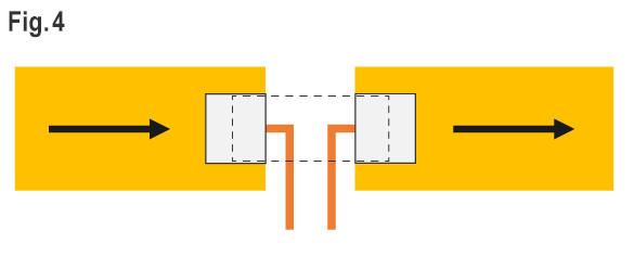
・Sensing lines laid out in the center of the resistor between the pads
General measurement method for 4 terminals
