DAC Basic Configurations 2 (Binary Method)
A circuit that receives and processes unconverted digital signals is referred to as a binary system.
Binary Method (Using Resistors)
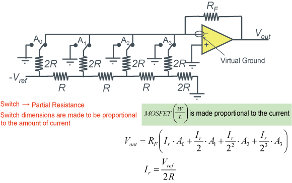
Binary systems provide weighted data to the circuit configuration, as shown below in the representative example of an R-2R ladder circuit.
R-2R ladder circuits appear as parallel connections of resistance values 2R from any node, resulting in half the current per node.

R-2R ladder D/A converter example
The following diagram shows an R-2R D/A converter with 4bit resolution.
This enables the creation of smaller D/A converters with up to 10 bit resolution (required resistors include 3N for Nbit D/A converter, and neither a decoder nor large switches are needed), and when combined with other methods resolutions up to 14bits are possible.
However, one drawback is that due to the high relative accuracy required for the resistors, both switch (MOSFET-sized) and layout optimizations (the R and 2R pair are important, and the MSB = A0 resistance must be accurately created) are required to achieve high precision operation.
Binary Method (Using Capacitors)
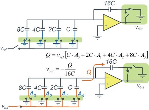
The conceptual diagrams below illustrate the concept of a D/A converter using capacitors.
This D/A converter requires use while switching.

D/A Converter using 2NC capacitors example
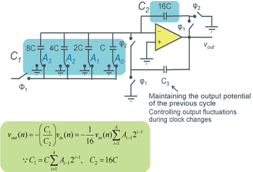
A 4bit D/A Converter utilizing capacitors is shown in the below diagram. Whichever switch (A0 to A3) falls on the Vref side will make it possible to obtain a different Vout voltage. When both switches on the amp at the right are turned on at the same time, the relationship with charge storage is lost, making it necessary to prevent ON-time overlap using clock signals.
The advantage of this method is that the high relative accuracy of capacitors makes high precision operation possible, plus DC current is not generated in the capacitors, enabling low current consumption at low frequencies since only the amp current flows.
The disadvantage is that higher speeds are not possible due to capacitor charging/ discharging, and refresh operation is required at low speeds in order to compensate for leakage current.
D/A Converter example utilizing 2NC capacitors(with refresh control)
4bit DAC with refresh control using capacitors
Binary method (Using resistors and capacitors)
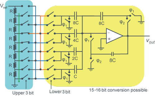
A 6bit resolution mixed type D/A converter can be configured using a 3bit resistor string D/A converter (left) and 3bit capacitor D/A converter.
Voltage across the resistors of the upper bits are weighted and compensated based on the data from the lower section.
The ability to obtain high resolutions provides a distinct advantage.
