Temperature Coefficient of Resistance ②
Why is the temperature coefficient of resistance specified in positive and negative values?
Many chip resistors specify the TCR in both positive and negative values, such as ±100ppm/℃ or ±200ppm/℃.
This indicates that the resistance value can change in either direction based on changes in temperature.
The reason is explained below using thick-film resistors as an example.
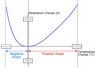
The temperature characteristics of thick-film chip resistors do not change linearly,but in a convex curve as shown in the following figure,with the horizontal and vertical axes represented by the change in temperature and resistance value, respectively.
This behavior is due to the temperature characteristics of the materials used in thick-film chip resistors.

Resistance Change Characteristics of a Typical Thick-Film Chip Resistor
The intersection of the horizontal and vertical axes in above graph is the reference temperature, which is typically the ambient temperature (25°C or 20°C).
In the case of the blue curve above, the slope between the positive and negative slopes is switched at the reference temperature in the center, with a negative slope in the region below this reference temperature as the resistance decreases with increasing temperature, and a positive slope in the area above the reference temperature as the resistance increases with increasing temperature.
However, please note that there will be variations at the vertices of the graph depending on the relationship between temperature and resistance of the actual resistive material.
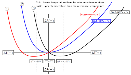
Let’s take the following curves as examples.
The graphs of ① to ③ below show the relationship between temperature and resistance in the same material. However, the positions of the vertices differ because the temperature coefficient of resistance changes depending on the production lot of the materials.
So as you can see, even if the same type of resistor is used in the same temperature range, variations in the temperature coefficient of resistance between production lots will affect the positive and negative characteristics of the resistance change rate.
[Ex]
・ Compare when the vertices of the graph are ① -80℃, ② ±0℃, and ③ +100℃, respectively
→ What kind of resistance change is shown at -80℃ to ±0℃ and ±0℃ to +100℃ for ① ~ ③?

Resistance Change Behavior Between Lots
| -80℃ to ±0℃ (Cold) | ±0℃ to +100℃ (Hot) | |
|---|---|---|
| Lot ① | Positive slope as the resistance increases with temperature | Positive slope as the resistance increases with temperature |
| Lot ② | Negative slope with the resistance decreasing as the temperature rises | Positive slope as the resistance increases with temperature |
| Lot ③ | Negative slope with the resistance decreasing as the temperature rises | Negative slope with the resistance decreasing as the temperature rises |
As the above shows, the temperature coefficient of resistance can change both positively and negatively depending on the behavior of the individual product even in the same temperature range.
Differences in the Temperature Coefficient of Resistance between Thick-Film and Metal Plate Resistors
Thus far, we have described the temperature coefficient of resistance of thick-film chip resistors, but metal plate resistors are another popular option.
Basically, metal plate chip resistors feature a smaller temperature coefficient of resistance than thick-film resistors.
Thick-film chip resistors primarily use silver as the electrode material, which has an extremely high temperature coefficient of resistance.
At the same time, the lower the resistance, the more silver is used in the resistive element.
Consequently, the temperature coefficient of resistance is higher at lower resistances.
Metal plate chip resistors, however, mainly use copper or copper plating as the electrode material.
Although copper also has a high temperature coefficient of resistance, the resistive element differs considerably.
The material used for the resistive element of metal plate resistors is a special alloy comprised of several different metals.
This alloy has a low temperature coefficient of resistance, which constitutes the main reason for the difference between thick-film and metal plate resistors.
Cross-Sectional Diagram of a Thick-Film Chip Resistor (MCR Series)

Cross-Sectional Diagrams of Metal Plate Resistors: PMR Series (left), PSR Series (right)

Temperature Coefficient of Resistance (TCR) Calculation Tool
The next page provides a brief explanation on how to use the Temperature Coefficient of Resistance (TCR) Calculation Tool.


