Basic Operation of an A/D Converter
Now, let’s take a look at the basic operation of an A/D converter.

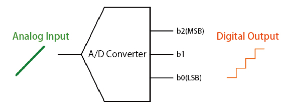
The A/D converter breaks up (samples) the amplitude of the analog signals at discrete intervals, which are then converted into digital values. Analog devices, such as audio and video equipment, often require ADCs to connect with modern digital systems, enhancing their functionality and compatibility. The resolution of an analog to digital converter (indicating the number of discrete values it can produce over a range of analog values) is typically expressed by the number of bits. In the above case of a 3bit A/D converter, the upper value (b2) is referred to as the Most Significant Bit (MSB) and the lowest value (b0) the Least Significant Bit (LSB). Digital data is crucial in this conversion process, as it allows devices like microcontrollers to interpret signals effectively.
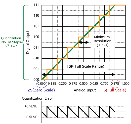
Digital signal processing is essential for converting natural phenomena into digital signals through ADCs and processing these signals in various applications. The graph below shows the relationship between the analog input signal and digital output. The input signal must be accurately measured to ensure proper conversion and prevent issues such as aliasing.
In addition, the first digital change point (000→001) below 0.5LSB is the zero scale, while the last digital change point (110→111) is termed full scale and the interval from zero to full scale referred to as the full scale range. Accurately capturing and reconstructing the original analog signal is vital during the digitization process, as sampling rates and resolutions impact the fidelity of the converted digital signals.

Analog Signal to Digital Signal Conversion Methods Using Analog to Digital Converters
- Sampling:
- Sampling is the process of taking amplitude values of the continuous analog signals at discrete time intervals (sampling period Ts).
[Sampling Period Ts = 1/Fs (Sampling Frequency)]
Sampling is performed using a Sample and Hold (S&H) circuit. - Quantization:
- Quantization involves assigning a numerical value to each sampled amplitude value from a range of possible values covering the entire amplitude range (based on the number of bits).
[Quantization error: Sampled Value - Quantized Value] - Coding:
- Once the amplitude values have been quantized they are encoded into binary using an Encoder.


