Chip Resistor Failure Example
Destruction Due to Overload
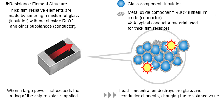
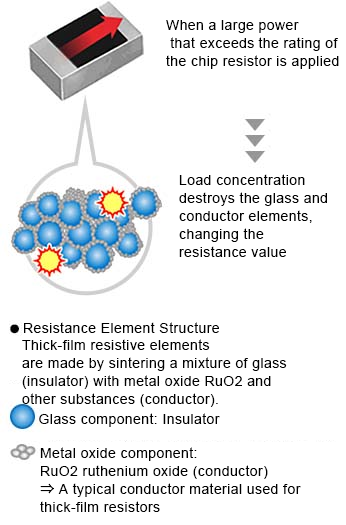
Overload Failure Mechanism
This section describes the failure case when power (voltage) exceeding the specifications is applied to a chip resistor.
When large power (voltage) that significantly exceeds the specified value is applied to the chip resistor,
current will be concentrated in the area below the laser trimming groove①. (Circled region below)
Subsequently, joule heating in this area will cause the localized temperature to rise.
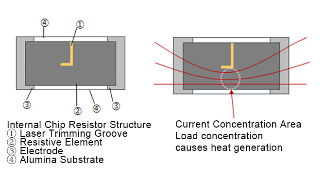
Heat dissipation occurs through the alumina substrate and other paths at the same time.
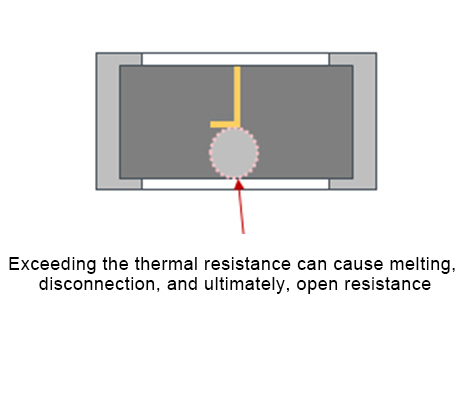
If the amount of heat dissipated is less than the amount generated, the thermal resistance of the resistive element and protective film may be exceeded, causing partial melting which can lead to localized disconnection.
And if the applied voltage is high, the remaining portion of the laser trimming groove will melt completely, resulting in disconnection (open resistance).
Furthermore, if the load is too large, the main body may crack.
Example of Resistance Change when Overvoltage is Applied
Generally, when overvoltage is applied to a chip resistor, the resistance goes negative first, then positive when a higher load is applied, eventually leading to disconnection (open).
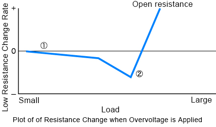
- ① Initial Overload
The insulating component (glass) in the resistor is destroyed and the resistance value drops.
(At this time, it will be in a shorted state) - ② Late-stage overload ⇒ Open failure
Heat generation leads to localized melting of the conductor component, while current concentration in the remaining conductor portion causes additional melting, resulting in an open circuit
