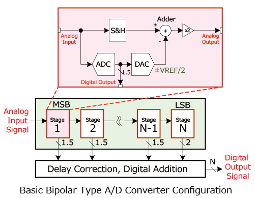
ADC Basic Configurations 2 (Pipeline Method)
In the case of a 1.5bit/stage configuration, the following processes are repeated in order from Stage 1 that determines MSB via pipeline operation (VREF: Reference Voltage).
- Analog input is sampled (using an S&H circuit)
- At the same time the analog input is converted by an A/D converter into a 3-value digital format (1.5bit). (Here the digital output stage is defined.)
- Analog input ≦ -VREF/4 → D="00"
- -VREF/4 < Analog input ≦ +VREF/4 → D="01"
- +VREF/4 < Analog input →D="10"
- These digital values are then converted into analog values using a digital to analog converter (DAC).
- D="00" → DAC output:-VREF/2
- D="01" → DAC output:0
- D="10" → DAC output:+VREF/2
- The negative DAC output voltage is amplified (x2) and output to the next stage.
Once processing of Stage N that determines LSB is completed, the delay between each stage is corrected then digital conversion completed by adding the respective digital output.

Characteristics:
- High resolution enabled (up to 16bit)
- High-speed conversion possible (200MHz max. sampling frequency)
- There is a necessary wait time until the digital signal is output (based on bipolar operation), making this impractical for applications requiring real-time processing (i.e. control).


