Precautions When Using Chip Resistors
Factors that Affect TCR ④
Factor ④ Misalignment Between Current Path and Sensing Lines
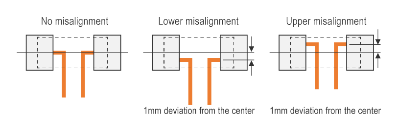
Laying out sensing lines at the center of the pads can suppress the effects on TCR, which is also affected by current path.
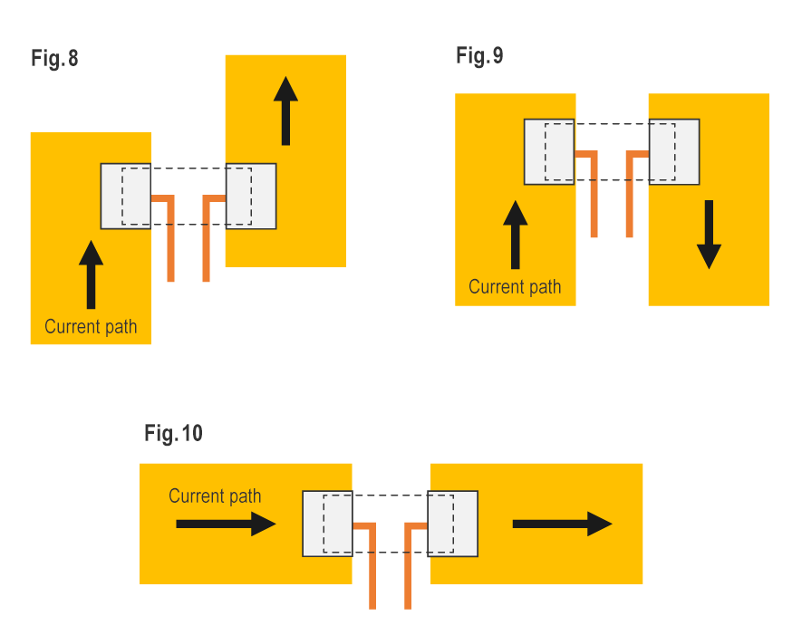
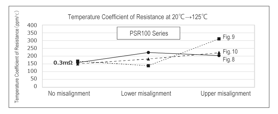
As an example, we compare the TCR (20°C to 125°C) of a 0.3mΩ PSR100 under three current path conditions (see Figs. 8-10 below).
This comparison is based on the assumption that there may be some degree of misalignment of the sensing lines from the center of the pads and accuracy of board construction.
The result shows that the effects on TCR caused by misalignment between the product and sensing lines can vary depending on current path.
In the case of Fig. 9, it can be said that a design that shifts the position of the sensing lines from the center of the pads to the bottom beforehand translates to a more advantageous TCR.


