SiC MOSFETs
SiC MOSFETs eliminate tail current during switching, resulting in faster operation, reduced switching loss, and increased stabilization. Lower ON resistance and a compact chip size result in reduced capacitance and gate charge. In addition, SiC exhibits superior material properties, such as minimal ON-resistance increases, and enables greater package miniaturization and energy savings than silicon (Si) devices, in which the ON resistance can more than double with increased temperature.
ROHM’s 4th Generation SiC MOSFET
Our latest 4th Gen SiC MOSFETs provide industry-leading low ON resistance with improving short-circuit withstand time. Additional features include low switching loss and support for 15V gate-source voltage that contributes to further device power savings.
This application note describes the features of the 4th Gen SiC MOSFET discrete package products and explains in more detail how to obtain their maximum performance.
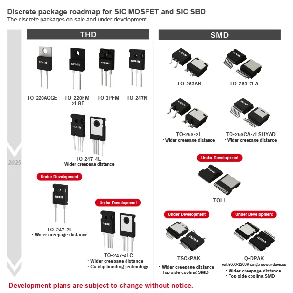
Discrete package roadmap for SiC MOSFET and SiC SBD
The discrete packages on sale and under development.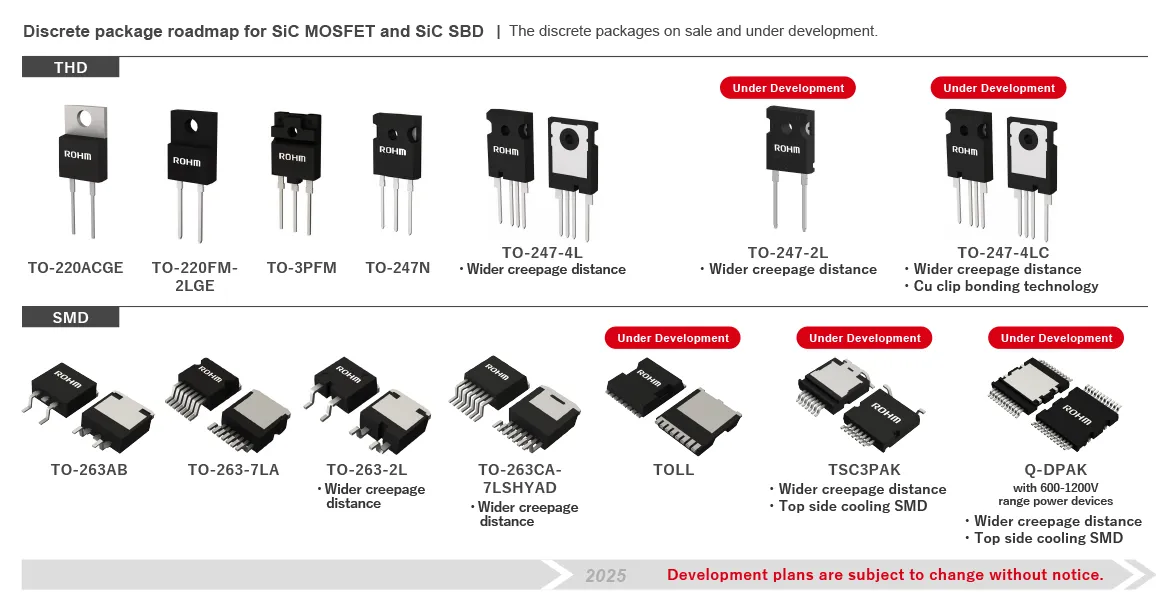
Easy Part Finder
Parametric Search
Supporting Information
- ROHM 4th Gen SiC MOSFETs
- Supporting Content for ROHM 4th Gen SiC MOSFETs
- Supporting Content for SiC MOSFET
ROHM 4th Gen SiC MOSFETs
Our latest 4th gen SiC MOSFETs provides industry-leading low ON resistance with improving short-circuit withstand time. Additional features include low switching loss and support for 15V gate-source voltage that contributes to further device power savings.
Key Features
1.Achieves industry-leading low ON resistance with improving short-circuit ruggedness
Nevertheless, with 4th Gen SiC MOSFETs, ROHM has successfully reduced ON resistance by 40% compared to conventional products with improving short-circuit ruggedness, through device structure improvements based on its original double-trench design. The result: is a robust power switching device with the lowest ON resistance in the industry. (ROHM Feb 2022 study)
2.Minimizes switching loss by drastically reducing parasitic capacitance
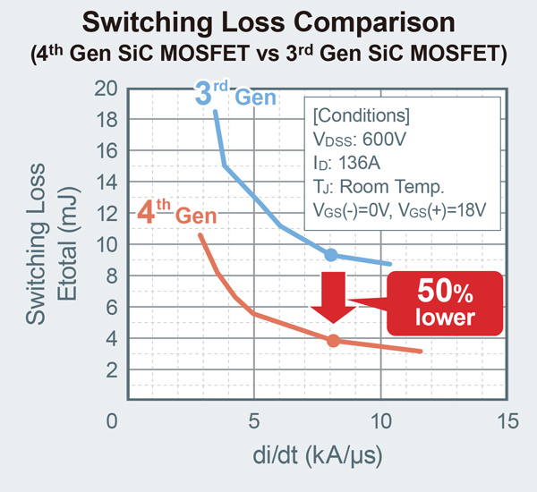
ROHM’s 4th Gen MOSFETs achieve 50% lower switching loss over conventional products by significantly reducing the gate-drain capacitance (Cgd).
3.Supports 15V Gate-Source voltage, improving application design freedom
In contrast to the 18V Gate-Source voltage (Vgs) required in the 3rd Generation and earlier SiC MOSFETs, these 4th Gen products support a more flexible gate voltage range (15-18V), enabling to design a gate drive circuit that can also be used for IGBTs.

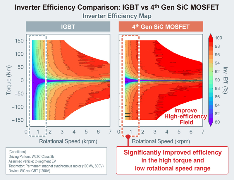
Application Example: Traction Inverter
6% electricity consumption reduction can be achieved over IGBT solutions by significantly improving the efficiency mainly in the high torque and low rotational speed range when the 4th Gen. SiC MOSFET is used in the traction inverters (calculated using the WLTC fuel economy test, an international standard).
Supporting Content for ROHM 4th Gen SiC MOSFETs
Evaluation board
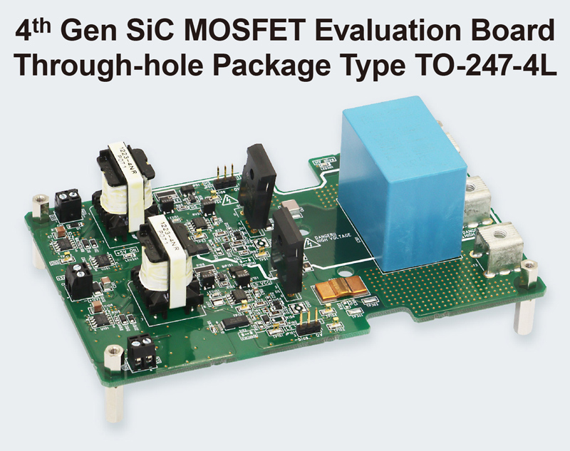
4th Generation SiC MOSFET Half Bridge Evaluation Board
P04SCT4018KE-EVK-001/P05SCT4018KR-EVK-001
The P04SCT4018KE-EVK-001/P05SCT4018KR-EVK-001 series of evaluation boards were developed for TO-247N/TO-247-4L package 4th gen SiC MOSFETs. Onboard gate driver and peripheral circuits reduce the number of man-hours required for design and evaluation.
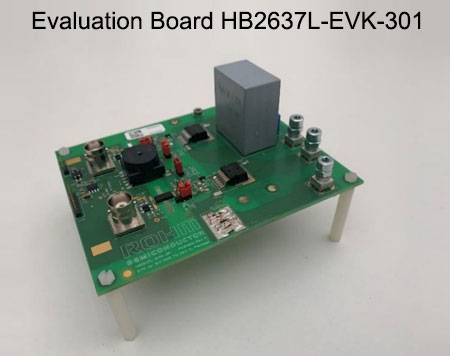
Evaluation Board HB2637L-EVK-301
The evaluation board is configured in a half bridge set up and thus allows evaluations in different operations modes such as buck, boost, synchronous buck/boost and inverter operations. The board is equipped with two SiC MOSFETs(SCT4036KW7), isolated gate driver BM61S41RFV-C, isolated power supply required for the gate driver, LDO for 5V supply and easy to interface connectors for PWM signals.
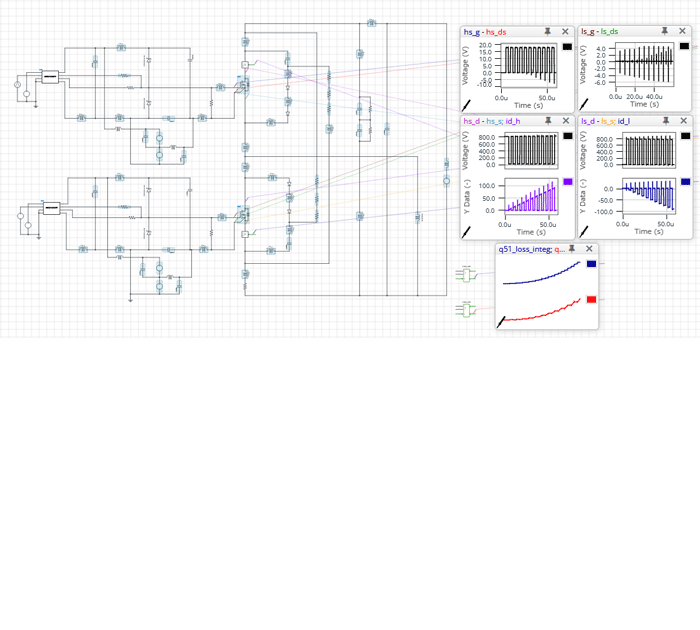
EVK Simulatrion (ROHM Solution Simulator)
・P05CT4018KR-EVK-001 Double Pulse Test
・P04SCT4018KE-EVK-001 Double Pulse Test
・HB2637L-EVK-301 Double Pulse Test
We have released the double-pulse test simulation environment with the evk simulation model.
The simulation circuit includes EVK's pattern parasitic inductor and can simulate the operating waveforms of 4G-SiC MOSFETs with high accuracy. Simulation conditions such as operating voltage, gate drive circuit, and snubber circuit constants can also be changed. It can be used to reduce man-hours during evaluation of actual devices and for verification before board prototyping.
Documents
White Paper
- 4 Steps for Successful Thermal Designing of Power Devices
- New SPICE Models with ImprovedSimulation Speed for PowerSemiconductors Are Released!
Application Note
- 4th Gen SiC MOSFETs Discrete Package:Characteristics and Precautions for Circuit Design Application Note
- 5kW Inverter Circuit Using 4th Generation SiC MOSFETs
- Application Benefits of Using 4th Generation SiC MOSFETs
Design model
| Part Number | Drain-source Voltage[V] | Drain-source On-state Resistance (Typ.(mΩ) |
Package | SPICE Model? |
PLECS Model? |
PSIM Model? |
PCB Library? |
| SCT4045DE | 750 | 45 | TO-247N |
||||
| SCT4026DE | 26 | ||||||
| SCT4013DE | 13 | ||||||
| SCT4062KE | 1200 | 62 | |||||
| SCT4036KE | 36 | ||||||
| SCT4018KE | 18 | ||||||
| SCT4045DR | 750 | 45 | TO-247-4L |
||||
| SCT4026DR | 26 | ||||||
| SCT4013DR | 13 | ||||||
| SCT4062KR | 1200 | 62 | |||||
| SCT4036KR | 36 | ||||||
| SCT4018KR | 18 | ||||||
| SCT4045DW7 | 750 | 45 | TO-263-7L |
||||
| SCT4026DW7 | 26 | ||||||
| SCT4013DW7 | 13 | ||||||
| SCT4062KW7 | 1200 | 62 | |||||
| SCT4036KW7 | 36 | ||||||
| SCT4018KW7 | 18 |
Simulations (Login Required)
- [4th Gen SiC] D-001. P05SCT4018KR-EVK-001 Double Pulse Test
- [4th Gen SiC] D-002. P04SCT4018KE-EVK-001 Double Pulse Test
- [4th Gen SiC] D-003. HB2637L-EVK-301_SCT4036KW7 Double Pulse Test
TO-247N (3pin)
- [4th Gen SiC] A-011b. Totem-pole PFC Vin=220V Vout=400V Pout=3.3kW
- [4th Gen SiC] C-016b. LLC Full-Bridge Vin=400V Vout=500V Pout=3.3kW
TO-247-4L (4pin)
SiC MOSFET Support Content
Evaluation Board
| Category | SiC Product | Image | Part No. | User Guide | Purchase Board |
|
| SiC-MOS | Evaluation Board |
SCT4XXX series Trench(4th Generation) TO-247-N | 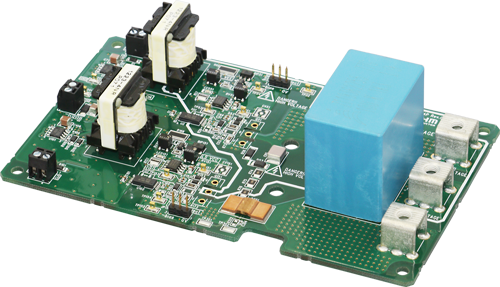 |
NEW P04SCT4018KE-EVK-001 |
User Guide Product Specification |
Online Distributors |
| SCT4XXX series Trench(4th Generation) TO-247-4L | 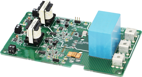 |
NEW P05SCT4018KR-EVK-001 |
Online Distributors |
|||
| SCT3XXX series Trench(3rd Generation) TO-247-4L |  |
P02SCT3040KR-EVK-001 | User Guide Product Specification |
Online Distributors |
||
Documents
White Paper
- 4 Steps for Successful Thermal Designing of Power Devices
- Cutting-Edge Web Simulation Tool “ROHM Solution Simulator” Capable of Complete Circuit Verification of Power Devices and Driver ICs
- The Problem with Traditional Vaccine Storage Freezers and How ROHM Cutting-edge Power Solutions Can Take them to the Next Level
- LEADRIVE: Design, Test And System Evaluation Of Silicon Carbide Power Modules And Motor Control Units
- Solving The Challenges Of Driving SiC MOSFETs With New Packaging Developments
Application Note
- 4th Gen SiC MOSFETs Discrete Package:Characteristics and Precautions for Circuit Design Application Note
- 5kW Inverter Circuit Using 4th Generation SiC MOSFETs
- Application Benefits of Using 4th Generation SiC MOSFETs
- 5kW High-Efficiency Fan-less Inverter
- 800V Three-Phase Output LLC DC/DC Resonant Converter
- Improvement Of Switching Loss By Driver Source
- Basics and Design Guidelines for Gate Drive Circuits
Technical Articles
Schematic Design & Verification
- New SPICE Models with ImprovedSimulation Speed for PowerSemiconductors Are Released!
- Oscillation countermeasures for MOSFETs in parallel
- Application Note for SiC Power Devices and Modules
- Calculating Power Loss from Measured Waveforms
- Calculation of Power Dissipation in Switching Circuit
- Method for Monitoring Switching Waveform
- Precautions during gate-source voltage measurement for SiC MOSFET
- Snubber circuit design methods for SiC MOSFET
- Gate-source voltage behaviour in a bridge configuration
- Gate-Source Voltage Surge Suppression Methods
- Importance of Probe Calibration When Measuring Power: Deskew
- Impedance Characteristics of Bypass Capacitor
- Basics and Design Guidelines for Gate Drive Circuits
- SiC MOSFET Layout Design Considerations
- Best practices for the connection of Driver Source/Emitter terminals in discrete devices
Thermal Design
- What Is Thermal Design
- Basics of Thermal Resistance and Heat Dissipation
- Method for Calculating Junction Temperature from Transient Thermal Resistance Data
- Notes for Temperature Measurement Using Thermocouples
- Two-Resistor Model for Thermal Simulation
- Notes for Temperature Measurement Using Forward Voltage of PN Junction
- What is a Thermal Model? (SiC Power Device)
- How to Use Thermal Models
- Measurement Method and Usage of Thermal Resistance RthJC
- Precautions When Measuring the Rear of the Package with a Thermocouple
Models & Tools
Simulations (Login Required)
ROHM Solution Simulator is a new web-based electronic circuit simulation tool that can carry out a variety of simulations, from initial development that involves component selection and individual device verification to the system-level verification stage. This makes it possible to quickly and easily implement complete circuit verification of ROHM power devices and ICs, in simulation circuits under close to actual conditions, significantly reducing application development efforts.
TO-247N (3pin)
- [4th Gen SiC] A-011b. Totem-pole PFC Vin=220V Vout=400V Pout=3.3kW
- [4th Gen SiC] C-016b. LLC Full-Bridge Vin=400V Vout=500V Pout=3.3kW
TO-247-4L (4pin)
- [4th Gen SiC] A-011a. Totem-pole PFC Vin=220V Vout=400V Pout=3.3kW
- [4th Gen SiC] C-016a. LLC Full-Bridge Vin=400V Vout=500V Pout=3.3kW
- [4th Gen SiC] D-001. P05SCT4018KR-EVK-001 Double Pulse Test
- [4th Gen SiC] D-002. P04SCT4018KE-EVK-001 Double Pulse Test
- [4th Gen SiC] D-003. HB2637L-EVK-301_SCT4036KW7 Double Pulse Test
- A-001. Boost PFC VIN=200V, IIN=2.5A BCM
- A-002. Boost PFC VIN=200V, IIN=2.5A CCM
- A-003. Boost PFC VIN=200V, IIN=2.5A CCM Synchronous FETs
- A-004. Boost PFC VIN=200V, IIN=2.5A DCM
- A-005. Boost PFC VIN=200V, IIN=2.5A DCM Synchronous FETs
- A-006. Interleaved PFC VIN=200V, IIN=2.5A CCM
- A-008. Interleaved PFC VIN=200V, IIN=2.5A DCM
- A-012. Diode-Bridgeless PFC VIN=200V, IIN=2.5A BCM
- B-011. 3-Phase 3-level NPC-T Inverter POUT=10kW
- B-012. 3-Phase 3-level NPC-I Inverter POUT=10kW
- C006. DC-DC Converter, Buck Converter Vo=250V Io=20A
- C007. DC-DC Converter, Buck Converter 2-Phase Vo=250V Io=40A
- C010. DC-DC Converter, Flyback Converter VIN=800V Vo=25V Io=10A
- C011. DC-DC Converter, Forward Converter VIN=500V Vo=25V Io=10A
- C012. DC-DC Converter, LLC Buck Converter Vo=12V Io=250A
- C013. DC-DC Converter, Phase-Shift Buck Converter Vo=12V Io=250A
- C014. DC-DC Converter, Quasi-Resonant Converter VIN=800V Vo=25 Io=10A
- ROHM Solution Simulator Power Device User's Guide for Inverter
Application
- Main Inverter (Traction Inverter)
- Bi-directional On-Board Charger (OBC)
- Solar Power Inverter (PV Inverter)
- Main Inverter (Traction Inverter)
Topology
Related Product

