SCT4013DR
750V, 13mΩ, 4-pin THD, Trench-structure, Silicon-carbide(SiC) power MOSFET
SCT4013DR
750V, 13mΩ, 4-pin THD, Trench-structure, Silicon-carbide(SiC) power MOSFET
SCT4013DR is a SiC MOSFET that contributes to miniaturization and low power consumption of applications. This is a 4th generation product that achieves industry-leading low on-resistance without sacrificing short-circuit withstand time. This is a 4-pin package type with a driver source terminal that can maximize the high-speed switching performance that is a feature of SiC MOSFETs.
Advantages of ROHM's 4th Generation SiC MOSFET
This series has about 40% reduction in on-resistance and about 50% reduction in switching loss compared to conventional products. The 15V gate-source voltage makes application design easier.
For Automotive usage, please contact Sales.
Product Detail
Specifications:
Drain-source Voltage[V]
750
Drain-source On-state Resistance(Typ.)[mΩ]
13
Generation
4th Gen (Trench)
Drain Current[A]
105
Total Power Dissipation[W]
312
Junction Temperature(Max.)[°C]
175
Storage Temperature (Min.)[°C]
-40
Storage Temperature (Max.)[°C]
175
Package Size [mm]
23.45x16.0 (t=5.2)
Features:
- Low on-resistance
- Fast switching speed
- Fast reverse recovery
- Easy to parallel
- Simple to drive
- Pb-free lead plating ; RoHS compliant
Reference Design / Application Evaluation Kit
-
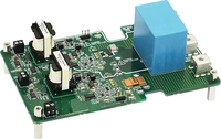
- Evaluation Board - P05SCT4018KR-EVK-001
- This board is designed with the optimum gate drive circuit for "SCT4018KR", surely TO-247-4L can also be evaluated
- Single power supply(+12V operation)
- Supports double pulse testing up to 150A and switching up to 500kHz
- Supports various power supply topologies(Buck, Boost, Half-Bridge)
- Built-in adjustable gate drive isolated power supply(positive and negative)(+12V to +25V, -4.5V to -2V)
- Active mirror clamp circuit(driver IC built-in type)
- Gate surge clamp circuit
-
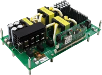
- Reference Design - REF68020
- 2.5kW LLC Converter, DC390Vin, 48Vout
LLC converters are power conversion circuits that utilize resonance phenomena, consisting of a primary-side excitation inductance, resonant inductor, resonant capacitor, switching element, and secondary-side rectifier circuit. By employing soft-switching technologies such as ZVS (Zero Voltage Switching) (primary-side switch) and ZCS (Zero Current Switching) (secondary-side switch), switching losses are significantly reduced, achieving high efficiency and low EMI by suppressing switching noise. They are applicable to a variety of power conversion circuits.
LLC converters that accept DC 400V input are used in applications where the DC voltage is converted from a commercial AC power input via a PFC (Power Factor Correction) and then converted to the voltage required by the system for distribution (server power supplies, industrial power supplies, PV hybrid inverters, ESS, UPS, xEV OBC (onboard charger), etc.), as well as for voltage conversion from the 400V battery of xEVs (xEV DC-DC converters, etc.). The secondary-side full-bridge rectifier circuit is a topology commonly used for relatively high power (up to several tens of kW) and relatively high output voltage (>48V).
This reference design is a DC 390V input, 48V output, 2.5kW LLC converter that incorporates Nuvoton Technology's high-resolution 32-bit MCU (KM1M7CF0) for power control and uses SiC MOSFETs as the primary switching element.
For more details about the board, please contact the following:
https://www.nuvoton.com/applications/power-energy/llc-reference-board/