
What is ROHM's sensor evaluation kit?
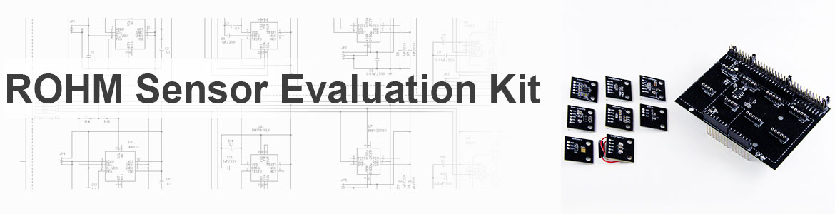
ROHM's sensor evaluation kit is compatible with open platforms such as Arduino and mbed.
The sensor shield enables easy evaluation of the 8 onboard high-performance sensors, making it ideal for verifying sensor operation, initial set development, and as a learning/training tool.
This site allows users to download sensor datasheets, manuals, and sample software.
Sensor Evaluation Kit
Click here for information on old products
| Sensor Evaluation Kit | Manual | Software (Go to license page) |
Onboard Sensor Part No. |
|---|---|---|---|
| Heart Rate Sensor BH1792GLC-EVK-001 | (1.01MB) |
(8.4KB) |
BH1792GLC (Obsolete) |
| Heart Rate Sensor BH1790GLC-EVK-001 | (692KB) Software(284KB) |
Sample Code (For Arduino)(4.05KB) HR Calculation Algorithm (For Arduino, Without Movement Cancellation)(30.7KB) |
BH1790GLC (Obsolete) |
| Color Sensor BH1749NUC-EVK-001 | (1.18MB) |
(4.1KB) |
BH1749NUC (Obsolete) |
| Geomagnetic Sensor BM1422AGMV-EVK-001 | (1.25MB) |
(4.2KB) |
BM1422AGMV (Last Time Buy) |
| Barometric Pressure Sensor BM1390GLV-EVK-001 | (525KB) |
(4.46KB) |
BM1390GLV (Last Time Buy) |
| Accelerometer Sensor KXTJ3-1057-EVK-002 | (641KB) |
(4.46KB) |
KXTJ3-1057 (Last Time Buy) |
| Ambient Light Sensor and Proximity Sensor RPR-0521RS-EVK-001 | (1.27MB) |
(4.66KB) |
RPR-0521RS |
| Shield for Arduino SHIELD-EVK-001 | (543KB) |
- | - |
Sensor Evaluation Kit SensorShield-EVK-003
| Board | Manual | Software (Go to license page) |
Onboard Sensor Part No. |
|---|---|---|---|
| Accelerometer Sensor KX224-I2C-EVK-001 | (755KB) |
(4.15KB) |
KX224-1053 (Last Time Buy) |
| Barometric Pressure Sensor BM1383AGLV-EVK-001 | (1.23MB) |
(4.12KB) |
BM1383AGLV (Obsolete) |
| Geomagnetic Sensor BM1422AGMV-EVK-001 | (1.25MB) |
(4.2KB) |
BM1422AGMV (Last Time Buy) |
| Ambient Light Sensor and Proximity Sensor RPR-0521RS-EVK-001 | (1.27MB) |
(4.66KB) |
RPR-0521RS |
| Color Sensor BH1749NUC-EVK-001 | (1.18MB) |
(4.1KB) |
BH1749NUC (Obsolete) |
| Hall Effect Sensor BD7411G-EVK-001 | (1.15MB) |
(3.01KB) |
BD7411G |
| Temperature Sensor BD1020HFV-EVK-001 | (1.13MB) |
(3.25KB) |
BD1020HFV |
| Heart Rate Sensor BH1790GLC-EVK-001 | (692KB) Software(284KB) |
Sample Code (For Arduino)(4.05KB) HR Calculation Algorithm (For Arduino, Without Movement Cancellation)(30.7KB) |
BH1790GLC (Obsolete) |
| Shield for Arduino SHIELD-EVK-001 | (543KB) |
- | - |
Sensor Evaluation Kit SensorShield-EVK-002
| Board | Manual | Software (Go to license page) |
Onboard Sensor Part No. |
|---|---|---|---|
| Accelerometer Sensor KX224-I2C-EVK-001 | (755KB) |
(4.15KB) |
KX224-1053 (Last Time Buy) |
| Barometric Pressure Sensor BM1383AGLV-EVK-001 | (1.23MB) |
(4.12KB) |
BM1383AGLV (Obsolete) |
| Geomagnetic Sensor BM1422AGMV-EVK-001 | (1.25MB) |
(4.2KB) |
BM1422AGMV (Last Time Buy) |
| Ambient Light Sensor and Proximity Sensor RPR-0521RS-EVK-001 | (1.27MB) |
(4.66KB) |
RPR-0521RS |
| Color Sensor BH1747NUC-EVK-001 | - | - | BH1747NUC (Obsolete) |
| Hall Effect Sensor BD7411G-EVK-001 | (1.15MB) |
(3.01KB) |
BD7411G |
| Temperature Sensor BD1020HFV-EVK-001 | (1.13MB) |
(3.25KB) |
BD1020HFV |
| Heart Rate Sensor BH1790GLC-EVK-001 | (692KB) Software(284KB) |
Sample Code (For Arduino)(4.05KB) HR Calculation Algorithm (For Arduino, Without Movement Cancellation)(30.7KB) |
BH1790GLC (Obsolete) |
| Shield for Arduino SHIELD-EVK-001 | (543KB) |
- | - |
Sensor Evaluation Kit SensorShield-EVK-001
| Board | Manual | Software (Go to license page) |
Onboard Sensor Part No. |
|---|---|---|---|
| Accelerometer Sensor KX022-1020-EVK-001 | Circuit Diagram (ARDUINO_SCH)(95KB) |
(4.03KB) |
KX022-1020 (Last Time Buy) |
| Barometric Pressure Sensor BM1383GLV-EVK-001 | Circuit Diagram (ARDUINO_SCH)(95KB) |
(3.83KB) |
BM1383GLV (Obsolete) |
| Geomagnetic Sensor BM1422GMV-EVK-001 | Circuit Diagram (ARDUINO_SCH)(95KB) |
(4.37KB) |
BM1422GMV (Last Time Buy) |
| Ambient Light Sensor and Proximity Sensor RPR-0521RS-EVK-001 | (1.27MB) |
(4.66KB) |
RPR-0521RS |
| Color Sensor BH1745NUC-EVK-001 | Circuit Diagram (ARDUINO_SCH)(95KB) |
(5.22KB) |
BH1745NUC (Obsolete) |
| Hall Effect Sensor BD7411G-EVK-001 | (1.15MB) |
(3.96KB) |
BD7411G |
| Temperature Sensor BD1020HFV-EVK-001 | (1.13MB) |
(3.25KB) |
BD1020HFV |
| UV Sensor ML8511A-EVK-001 | Circuit Diagram (ARDUINO_SCH)(95KB) |
(3.28KB) |
ML8511A (Obsolete) |
| Shield for Arduino SHIELD-EVK-001 | (543KB) |
- | - |