Attention to Internet Explorer users: ROHM website does not recommend browsing in IE 11. Please use latest browser to ensure the best performance on ROHM website.
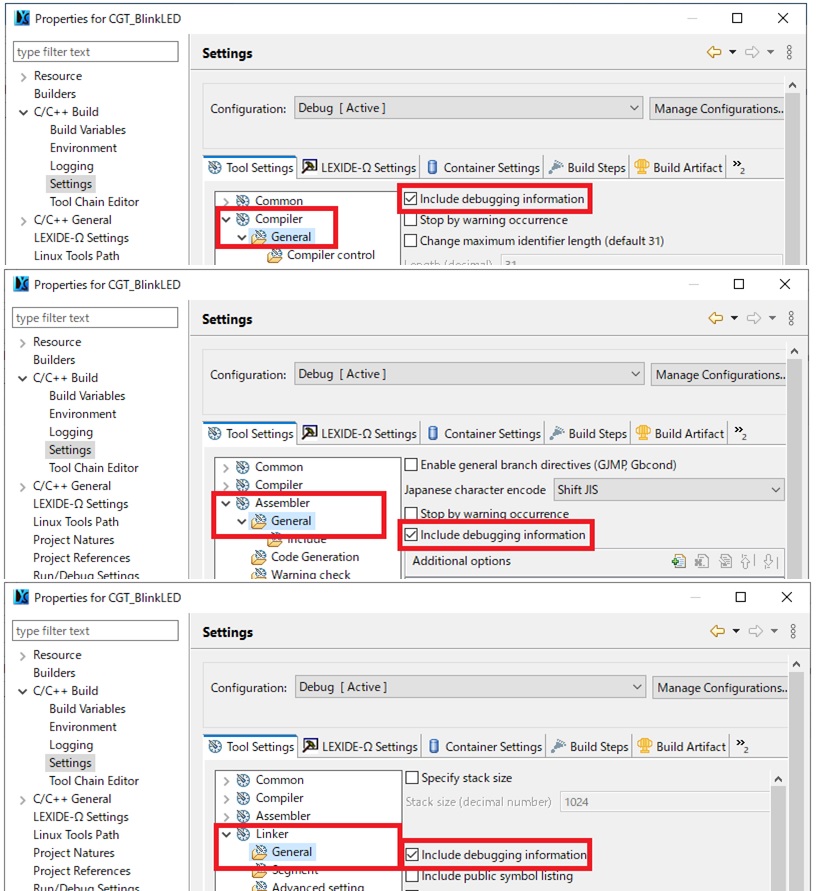
It is assumed that the .abs file does not contain any debugging information.
Please check whether the Compiler/Assembler/Linker settings in the Properties dialog of LEXIDE-Ω are set to include debug information.
Access may be blocked by your PC's security.
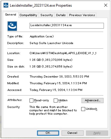
Right-click the installer executable file (LexideInstaller_xxxxxxxx.exe) and select Properties to check the property information.
If "Security" is displayed as shown below, check "Unblock" and try double-clicking the installer executable file again.
If a break occurs during URAT communication, it is assumed that a communication error has occurred due to the UART stopping and communication being interrupted.
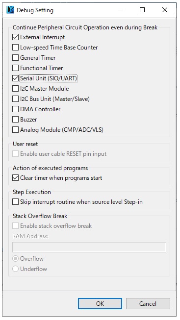
EASE1000 V2 allows you to select whether to "continue/stop" the operation of various peripherals during a break. Please use the setting to continue UART operation during break.
For peripheral settings at break, select [LAPIS Debug] > [Debug Setting...] in LEXIDE-Ω and check [Serial Unit(SIO/UART)] in the dialog that appears.
Additionally, if you do not want peripherals to stop during a break, such as when controlling a motor using a peripheral, we recommend using settings that allow the peripheral to continue operating during a break.
Object Converter (OHU8): Software that converts absolute object files to Intel HEX format or Motorola S2 format.
HEX Converter (HTU8): This is software that generates ROM code for writing the customer's program data to flash ROM or mask ROM, such as filling the empty area where no instruction code is placed with 0xFF, as input the file output by Object Converter OHU8.
The output file of Object Converter is treated as an intermediate file, and the output file of HEX Converter is the final file used for mass production.Make settings to output both Object Converter and HEX Converter.
There are two types of breakpoints: hardware breakpoints that use the break circuit built into the real LSI, and software breakpoints that are realized by replacing the program memory (code) built into the real LSI with break-specific instructions. Since software breakpoints rewrite/write back the internal flash memory of the real LSI, the response of emulation execution and step execution may be delayed.
Breakpoint settings are software breakpoints (Regular) by default, but you can change them to hardware breakpoints. However, please note that it is not possible to switch over the maximum number of hardware breakpoints, which is 4 points.
For details on how to change to a hardware breakpoint, please refer to "7.13.2 Adding and Deleting Conditional Breakpoints" in the LEXIDE User's Manual.
If you are using a reference software driver and all source files under the driver folder are included in the build, it may take a long time to build. In such cases, you may be able to save time by excluding unused driver source files from the build target.
To exclude unnecessary files from build targets, right-click an unnecessary file in the project on LEXIDE's [Project Explorer] and select [Resource Configurations] > [Exclude from build].
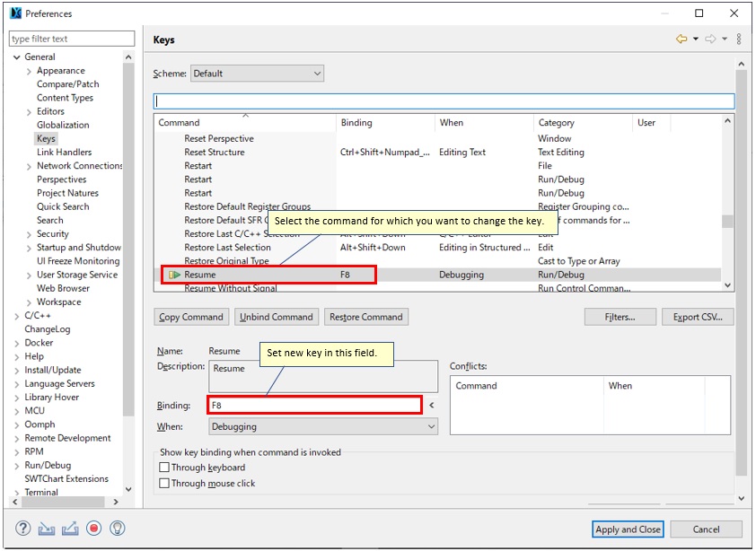
Function key assignments can be changed.
If you select General>Keys from the Preferences dialog that is displayed by selecting Window>Preferences in LEXIDE, a list of currently set assignments will be displayed on the Keys page.
Select the command for which you want to change the key assignment and change the settings in Binding. If there are duplicate key assignments, they will be displayed in Conflicts, so please change the duplicate commands as well.
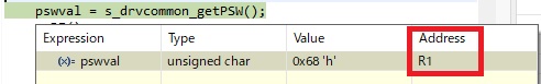
It is assumed that local variables are assigned to registers. When you hover your mouse over a local variable, a pop-up view appears and the assigned register is displayed in the Address field.
If a local variable is assigned to a register, change the value in the Registers view.
If a word register is displayed in the Address field of the popup view, it is a pair of byte registers. For example, if ER2 is displayed, enter the value of the upper 8 bits in R3 and the value of the lower 8 bits in R2.
For the configuration of general-purpose registers, refer to "1.2.1.1 General-purpose registers" in "nX-U16/100 Core Instruction Manual".
Two types are available. -Data flash driver "Simple version" -Data flash driver "EEPROM emulator version"
The "Simple version" is the "EEPROM emulator version" with the following functions omitted. (a) Abnormal data detection function using checksum (b) Logical address and physical address conversion function (c) A function to skip the defective bit and continue writing The "Simple version" has a smaller code size and faster processing time than the "EEPROM emulator version". Please select according to your purpose.
You can download it from support contents of our product site. When using ML62Q1000 series, please download "ML62Q1000 Series Reference Software". When using ML62Q2000 series, please download "ML62Q2000 Series Reference Software".
RAM variables can be assigned to fixed addresses using the segnoinit pragma and seginit pragma. The segnoinit pragma is a pragma for allocating variables without initialization, and the seginit pragma is a pragma for allocating variables with initialization to a specific area.
#pragma segnoinit 0xE000 /*Example1 */ int ni_var1; /*ni_var1 is allocated to address 0xE000 */ int ni_var2; /*ni_var2 is allocated to address 0xE002 */ #pragma segnoinit /* End of segnoinit pragma (optional) */
#pragma seginit 0xE100 /*Example1 */ int var1 = 0x1234; /*var1 is allocated to address 0xE100 */ int var2 = 0x5678; /*var2 is allocated to address 0xE102 */ #pragma seginit /* End of seginit pragma (optional) */
Please also refer to "How to Allocate Functions and Variables to Specific Areas" on our product site's support contents for the ML62Q1000 series.