Precautions When Using Chip Resistors
Factors that Affect TCR ③
Factor ③ Electrode/Pad Dimensions
For shunt resistors 10mΩ or less, depending on the position of the sensing lines, the TCR may differ even within the pads due to the effects of the copper foil and electrodes.
Generally, the lower the resistance the greater the effects.
Therefore, it is necessary to position the sensing lines in a way that reduces these effects as much as possible, even within the pad.
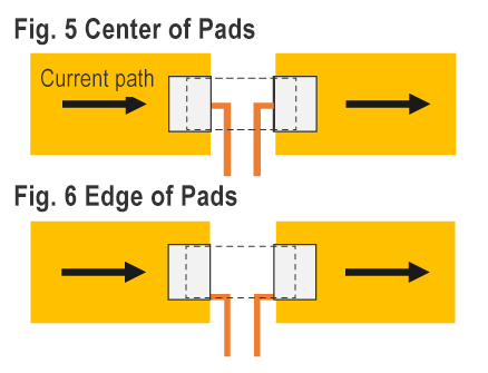
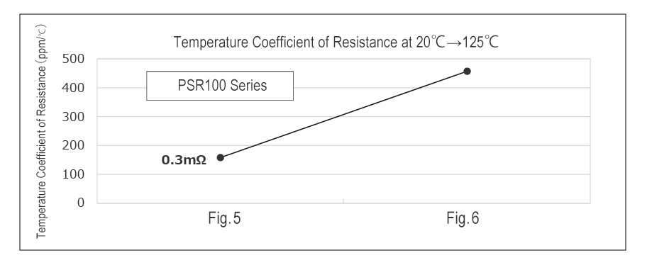
As an example, the TCR (20°C to 125°C) of a 0.3mΩ PSR100 is shown when the sensing lines are laid out in the center (Fig. 5) and edge (Fig. 6) of the pads.
When the sensing lines are positioned at the edge of the pads, the TCR rises due to the effects of the copper foil.
ROHM utilizes a layout that positions the sensing lines at the center of the pads.
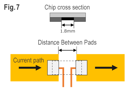
What's more, if the pad-to-pad distance differs from the electrode-to-electrode distance of the product, the TCR may also be affected.
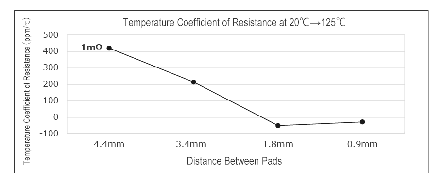
The following shows the TCR at different pad-to-pad distances for a 1mΩ PMR100.
When the pad-to-pad distance is larger than that of the electrodes, the contact area between the electrodes and pads becomes a factor, increasing the difference in TCR.
At the same time, if the distance between pads is too small, there will be insufficient space for laying out sensing lines, so a certain distance is necessary.