tr_What7
Junction Temperature
<Calculating Transistor Chip Temperature>
How to Calculate Junction Temperature (From Ambient Temperature)
Junction temperature (or channel temperature) can be calculated from the ambient using the following equation.
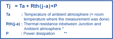
*Rth(j-a): Thermal resistance of "junction-to-ambient" varies depending on the type of circuit board. For reference, provided below is the Table of Thermal Resistance by Package"based on the use of ROHMs standard circuit board.
*Rth(j-a) value differs for each part number, but the values will be close if the package is the same.
**If the current consumption is not stable and changing time to time, then the averaged values of consumption current shall be assigned in the calculation formula to get the approximate value (See the "Usable or Not Judgement Method".
Below is an example of the correlation between current consumption and the junction temperature when Rth (j-a) is 250 deg./W , the ambient temperature is 25 deg.
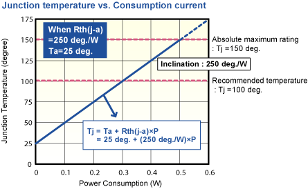
The junction temperature rises in proportion to the current consumption. The proportionality constant for this is Rth(j-a).
Since Rth(j-a) is 250 deg./W, the junction temperature rises by 25 deg. per each increment of 0.1W of current consumption. This means, the junction temperature becomes 150 deg. when the current consumption is 0.5W, and the graph in this case suggests that the current beyond 0.5W can not be applied to TR.
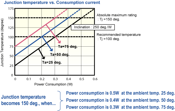
When the same current is applied, the junction temperature also rises as the ambient temperature goes up. This diminishes the applicable current subsequently. Maximum current consumption is influenced by thermal resistance and the ambient temperature as well.

The maximum current consumption decreases with the above ratio.
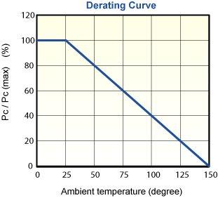
The Derating curve above illustrates the ratio of current attenuation by percentage, which can be applied to all packages. For example, in case of the MPT3 package (SOT89), the maximum applicable power is 0.5W at 25 deg. and the applicable current is reducing at a rate of 0.8%/deg. This means that the value goes down to 0.4W. That is 80% from 100% of its initial value (20% down), and then down to 0.2W which is 40% of its initial value (60% down).
Transient Thermal Resistance
In the examples above, we discussed cases in which the current is applied to a device continuously. Next, we will discuss a case in which the temperature rises by momentary current application.
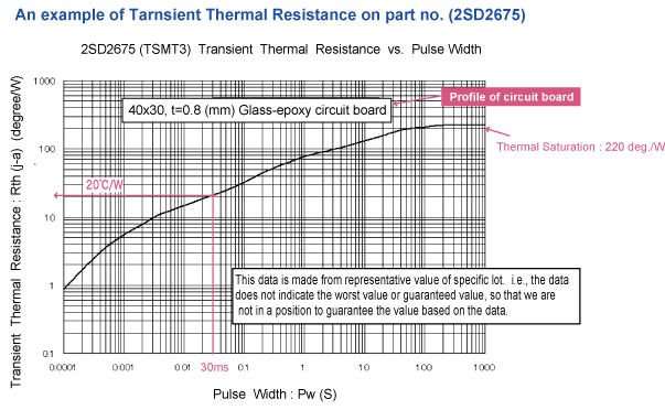
The graph above shows the thermal resistance at momentary time (Transient Thermal Resistance), plotting the pulse width on the X-axis and Rth(j-a) is on the Y-axis.
This graph shows us that the junction temperature rises as the current application time persists, reaching a plateau state (called thermal saturation) after 200 seconds.

We can use the calculation formula above to obtain the junction temperature when the current is applied momentarily as a single pulse.
Calculation Method of Junction Temperature (From Case Temperature)
The junction temperature can be calculated from the temperature of the case, as seen below. An example would be to replace Rth(j-a) in the formula with Rth(j-c).

* Case temperature is measured by the radiation thermometer, as the maximum temperature on the surface of the package, where the marking is put..
* Please note that the case temperature differs considerably depending on the measurement method/point.
** The value is considered an approximation when the applied current is not constant, shifting from time to time by assigning the averaged consumption figure.
Since the Rth(j-c) value varies depending on the types of circuit board and also on the heat dissipation conditions (which include soldering state), the formula above potentially wouldn't apply to your calculation since the the measured values on RHOMs circuit board may not be the same as the measured values on your circuit board. For instance, the case temperature could be lower in comparison even though the applied current is the same, when the circuit board has good heat dissipation characteristics.
An illustration below shows that Rth(j-c) becomes lower as the collector land pattern on the circuit board gets smaller. (Collector land area / thickness / materials plus circuit board material, size circuit width will also bring different measurement results on Rth(j-c).
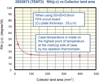
The Rth(j-c) value can differ depending on the nature & conditions of the circuit board. It is difficult to choose the right location for measuring the case temperature precisely. Because of this, it is not recommended to approximate the junction temperature from the case temperature.
Junction-to-Case Thermal Resistance Rth(j-c) - Details
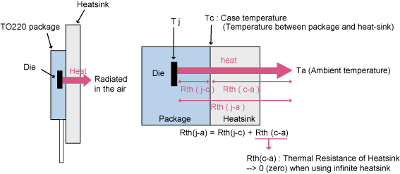
In principle, Junction-to-Case thermal resistance Rth(j-c) is an index basically used for TO220 packaged (through hole) devices by soldering it to the heatsink. In this case, since Case-to-Heatsink is the heat-radiation path, it is possible to precisely calculate the junction temperature by measuring the case temperature at the point in the middle of such path. In particular, if a heatsink with ideal heat dissipation performance is used (e.g. infinite heatsink), the heat dissipation capability is considered to be limitless. It is taken for granted that "Case temperature" = "Ambient temperature" , and Case temperature = 25 deg. (Tc = 25 deg.) is supplied in the calculation formula.
(Thermal resistance of infinite heat-sink : Rth(c-a) = ; then Rth(j-a) = Rth(j-c))
For surface-mount devices, the heat-radiation path is mainly the part of a circuit board that's just beneath the device; which can make it quite difficult to measure the case temperature because of the location. Even if the temperature on marking side of device is measured, its portion of heat-dissipation in the entire heat-dissipation is rather small. Therefore, it is not suitable to use this temperature within the formula to calculate the junction temperature.
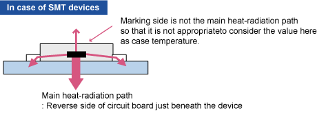
Nevertheless, since there are many requests from our customers about Rth(j-c) value for SMT devices, ROHM sometimes provides the Rth(j-c) value on the conditions that the temperature is measured from the marking side of the device being mounted on the previously mentioned standard circuit board. Because of this, the Rth(j-c) value should be considered as a reference.
If the device is mounted on the circuit board in a different way from ours, the portion of heat-dissipation in the entire heat radiation will be different, making it hard to figure out the junction temperature accurately.
Thermal Resistance of Standard Packages (Reference Data)
The values in following data are not the guaranteed values nor maximum / minimum values. Please treat these only as reference data.*
* Data listed here came from the results of measuring a specific production lot.
* Rth ( j-a ) varies depending on the circuit board, the heat-dissipation conditions involving soldering methods and the method of temperature measurement.
| Package | VMT3 | EMT3 | EMT5 | EMT6 | TUMT3 |
|---|---|---|---|---|---|
| Circuit Board |  |
 |
 |
 |
 |
| FR4 dimensions (unit:mm) |
20×12×0.8 | 20×15×0.8 | 20×15×0.8 | 20×15×0.8 | 20×12×0.8 |
| Rth(j-a)/ Rth(ch-a) |
833℃ / W | 833℃ / W | 1042℃ / W | 1042℃ / W | 313℃ / W |
| Note | - | - | When driving 1-die | When driving 1-die | - |
| Package | TUMT6 | UMT3 | UMT5 | UMT6 | SMT3 |
|---|---|---|---|---|---|
| Circuit Board |  |
 |
 |
 |
 |
| FR4 dimensions (unit:mm) |
15×20×0.8 | 20×12×0.8 | 20×15×0.8 | 15×20×0.8 | 20×12×0.8 |
| Rth(j-a)/ Rth(ch-a) |
313℃ / W | 625℃ / W | 1042℃ / W | 1042℃ / W | 625℃ / W |
| Note | When driving 1-die | - | When driving 1-die | When driving 1-die | - |
| Package | SMT5 | SMT6 | TSMT3 | TSMT5 | TSMT6 |
|---|---|---|---|---|---|
| Circuit Board |  |
 |
 |
 |
 |
| FR4 dimensions (unit:mm) |
20×15×0.8 | 20×15×0.8 | 30×15×0.8 | 20×15×0.8 | 20×15×0.8 |
| Rth(j-a)/ Rth(ch-a) |
625℃ / W | 625℃ / W | 250℃ / W | 250℃ / W | 250℃ / W |
| Note | When driving 1-die | When driving 1-die | - | When driving 1-die | When driving 1-die |
| Package | SOP8 | MPT3 | CPT3 | SST3 |  |
|---|---|---|---|---|---|
| Circuit Board |  |
 |
 |
 |
|
| FR4 dimensions (unit:mm) |
20×20×0.8 | 12×20×0.8 | 12×30×0.8 | 20×12×0.8 | |
| Rth(j-a)/ Rth(ch-a) |
160℃ / W | 250℃ / W | 125℃ / W | 625℃ / W | |
| Note | When driving 1-die | - | - | - |
electronics_tips_menu


