Rohm Breadcrumb

led_what6
LED Circuit Configuration
Forward Voltage
When current flows through an LED in the positive direction, the voltage generated between the anode and cathode is called the forward voltage (VF). The unit for voltage is volts (V).
In the datasheet for example, the characteristics graph of the forward voltage generated with respect to the current flow is provided (Forward Current IF vs Forward Voltage VF).
This characteristic is the most important parameter when considering the actual LED lighting circuit.
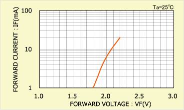 Forward Current (IF) - Forward Voltage (VF) Characteristics Example 1
The IF-VF characteristics will vary depending on the LED element material, size, and even emitting color. It will also vary depending on ambient temperature. In addition, there is a characteristics value distribution specific to semiconductors, what is known as variability.
Variations in VF are not problematic when the LEDs operate under constant current drive, but for constant voltage drive it is necessary to take these changes and fluctuations into account when designing.
LED Lighting Circuit
[In the case of a series lighting circuit]When lighting up LEDs in series via constant voltage drive, the circuit typically includes a resistor connected in series with the LEDs to control the current.
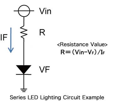
For this type of circuit, first read the forward current IF and forward voltage VF of the lit LED from the IF-VF characteristics.
The value of R (current control resistance) is determined through calculation by inputting these values in the above equation.
![[Parallel LED Lighting Circuit Example 1]](/documents/11303/6808215/img_led03.jpg/dff00306-bf69-dc8c-fccb-6197697eb864?t=1551850683147) [In the case of a parallel lighting circuit]
[In the case of a parallel lighting circuit]
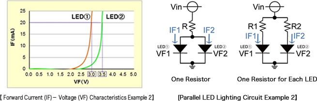
For parallel connection with constant voltage drive, we recommend a circuit configuration that utilizes a control resistor for each LED (which are arranged side by side in the above series lighting circuit).
LED IF-VF characteristics will vary depending on the element material and emitting color. Furthermore, individual variations inherent to semiconductors exist even when the material and emitting color are the same.
As shown in the graph below, when the VF of LED ① and LED ② differ, controlling the current with just one resistor makes it difficult to control the current flowing to each LED (IF1 and IF2).
Connecting a resistor to each LED allows the current flow to be set individually (IF1 and IF2), enabling customized settings (i.e. to achieve current matching, suppress brightness variations). In addition, applying a high voltage to the resistor, such as by increasing the input voltage Vin, makes it possible to implement design that takes into account variations.
electronics_tips_menu