ROHM’s latest SiC technology achieves excellent performance for electric vehicles
07/13/2018
Introduction
In recent years, in the automotive field in particular, EVs (Electric Vehicles) and HEVs (Hybrid Electric Vehicles) that do not emit CO2 are attracting attention, prompting the transition from gasoline powered vehicles. However, initiatives to improve energy saving performance in electric vehicles have increased the number of electronic components required. This leads to the expansion of the automotive devices market.
Although the automotive industry has been undergoing rapid advancement lately, ROHM has already been working continuously on the evolution of vehicles since the middle of 2000s. As of March 31st, 2018, the automotive sector accounted for 32% of the company’s net sales. To ensure the superior quality and stable supply required for the automotive industry, ROHM utilizes a vertically integrated system – a key advantage. It means that all manufacturing stages are carried out completely in-house, from pulling silicon ingots and producing photomasks to wafer processing, lead frame molding, and packaging. To increase the sales of products designed for automobiles, ROHM is now focusing on 4 categories: Powertrain, in-car infotainment systems, body and ADAS (Advanced Driver Assistance Systems). The results are solutions, which are optimized for each market and offer a broad lineup.
ROHM’s SiC Products and Application Examples
One striking example is silicon carbide (SiC) devices. ROHM has led the industry by beginning mass production of MOSFET products in 2010. And now, we have a product portfolio covering SiC Schottky Barrier Diodes, SiC MOSFETs, and a full range of SiC power modules, which integrate several semiconductor chips in a single package.
The leading automotive application for SiC devices is an on-board charger. It plays the role of AC-DC converters to charge up batteries with higher voltages, transforming from AC 100V to 240V DC voltage. The current products in the on-board charger have maximum allowable input voltages of 85V to 265V. Along with the market requirement of shorter charging times, higher allowable input voltages are also required with higher battery voltages, leading to stronger proliferation of SiC devices.
Another application example is DC-DC converters. In DC-DC buck converters, power transistors switch signals output from a higher voltage battery to convert to lower DC voltages through a transformer. SiC devices provide lower switching loss to enable DC-DC converters more efficient, and also to minimize peripheral component sizes.
Newly Developed Inverter
‘Everybody is working very hard by pushing the limit to increase the efficiency of the automotive system. It means that on inverter side and on motor side. We have to work a lot to reduce the weight because having a lighter car permits us to have a better vehicle dynamic behavior. It is really important to work on the best efficiency possible to lighter components.’ said Mr. Franck Baldet, chief technology officer of Venturi Formula E team. ‘The Inverter is one of the core parts in the car. I mean that inverter could control the motors. That is why it is very important on the design side for the electronic board, traffic components and obviously on power module that you integrate inside the inverter.’
As you can see from Franck’s comment, the inverter is one of the most important factors in the car. The following example shows, what happens when SiC devices are used in a main inverter.
Figure 1 shows two traction inverters. The left hand inverter is rated at 200kW and utilizes power modules with Si IGBTs and Si Fast Recovery Diodes (FRDs). This inverter is working in the field since 2013. The right hand inverter was newly developed utilizing full SiC modules and is rated for 220kW.
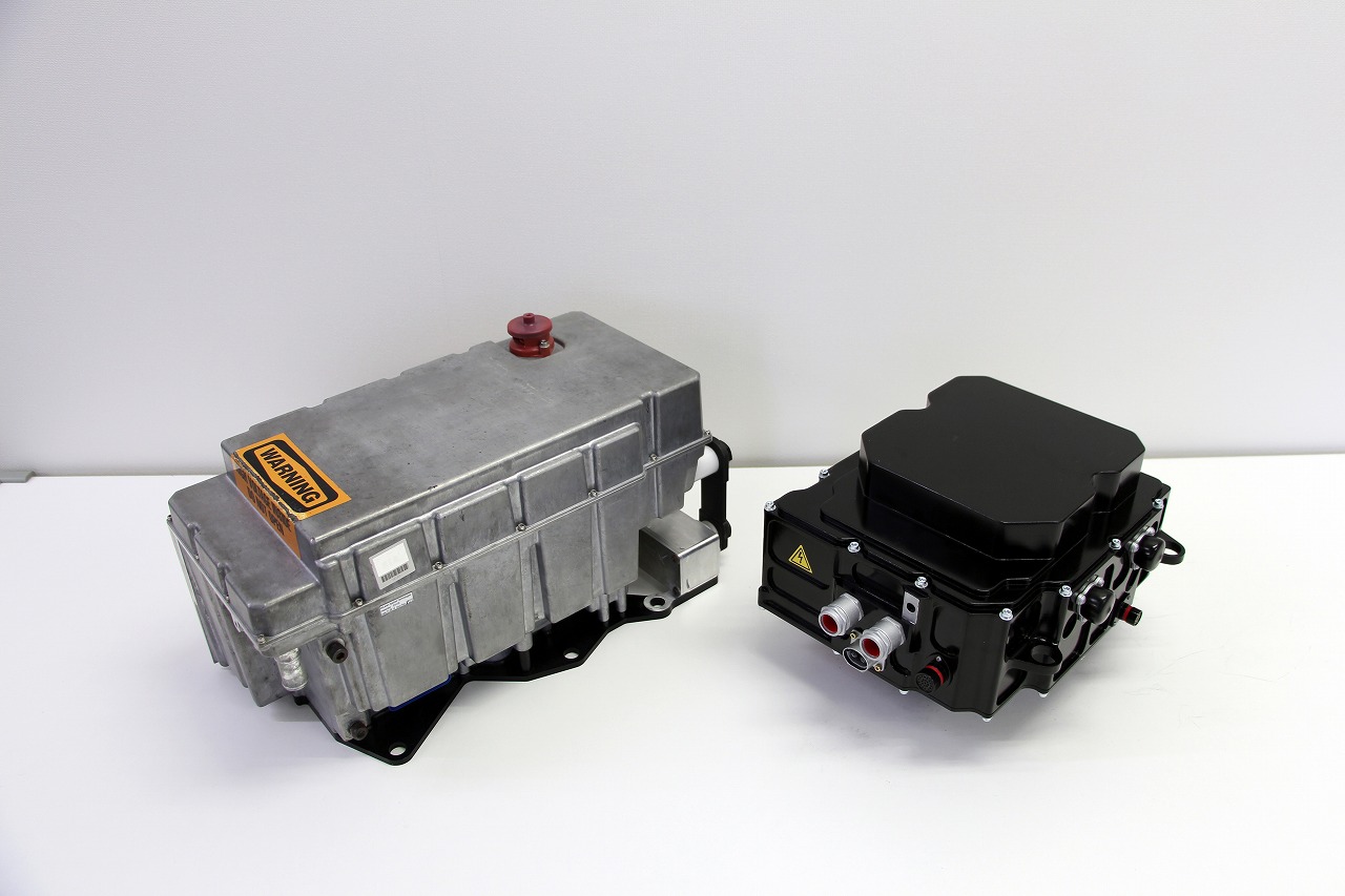
Figure 1. Inverter utilizing Si (Left) and SiC (Right)
Table 1 shows a specification comparison of both inverters. The new inverter utilizes variable switching frequency which can be varied depending on the motor operating point from 16kHz to 24kHz. Even in the lower rotor shaft speed range, the inverter utilizes 16kHz switching frequency to avoid the risk of resonance between the DC link capacitor and input cables. While the available maximum output power is 20kW higher the SiC MOSFET based inverter has lower volume and less weight than the Si IGBT based one. The weight is reduced by ca. 6kg and the volume is shrunk by 30% as well. These factors lead to realize a high power density inverter of 22kW/L, which is 57% higher than the conventional IGBT based solution.
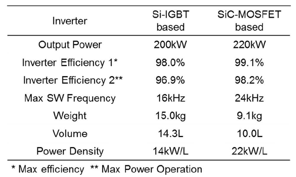
Table 1. Comparison of inverters parameters
In this power train system when operated in the high torque operation range (e.g. 170N・m) high currents above 500Arms are required to be provided by the module. This operation area has an important role during acceleration phase of the car. Figure 2 shows efficiency curve of two inverters at maximum torque operation. Over the entire area of the diagram the SiC MOSFET based inverter shows higher efficiency. At the 50kW and 100kW output power point, efficiency gap is around 5.0% and 2.5%, respectively.
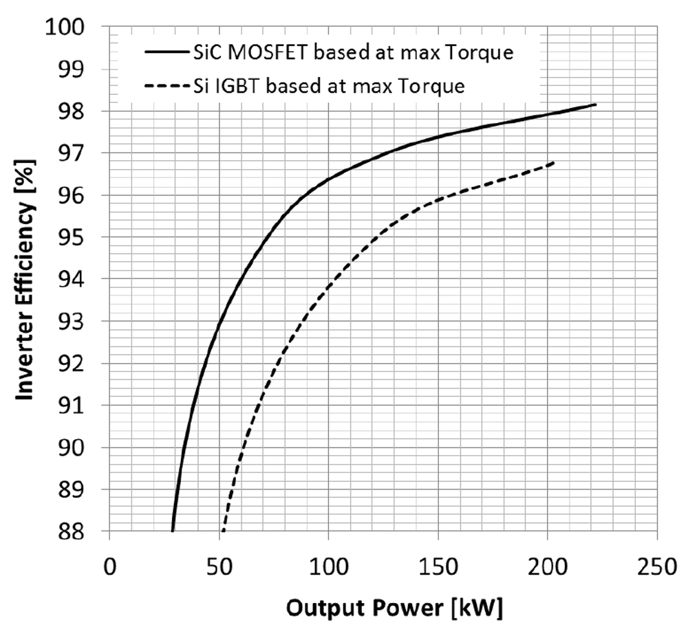
Figure 2. Inverter efficiency comparison at maximum torque operation
These reduced inverter losses equate to more power at the wheels of the car. In addition, lower losses lead to reduced chip temperature with the same cooling system. In these traction inverters set up, the main cooling system outside of the SiC MOSFET based inverter could shrink more than 30% compare to Si IGBT based inverter set up.
Furthermore, these improvements contribute to increasing the driving distance or reducing the battery volume if keeping same driving distance. The battery capacity reduction can lead to an economic benefit if the overall power train system is considered
Advanced Technology Competition in Formula E
The ABB FIA Formula E Championship is a great application example for our SiC devices. (See Photo 1)
‘Formula E is the world’s first fully-electric international single-seater street racing series, and there are many highlights. Obviously the DNA of the series racing in city centers is fantastic and it is also fantastic from a driver’s point of view because it is a real challenge on a street circuit to drive millimeters close to the wall, sometimes even touching the walls. And there is a lot of different strategies, which are available to us and which we have to choose from on how to go into the race and of course strategically keep an eye on the energy consumption.’ said Mr. Maro Engel, driver of Venturi Formula E team. ‘As a driver the most difficult aspect of Formula E racing is power management. It is the most difficult part of it compared to the other racing series. You cannot go flat out all the time; you have to develop some different driving skills to be fast but also to be efficient at the same time.’ Mr. Edoardo Mortara, drivers of this team described the difficulty of this race.
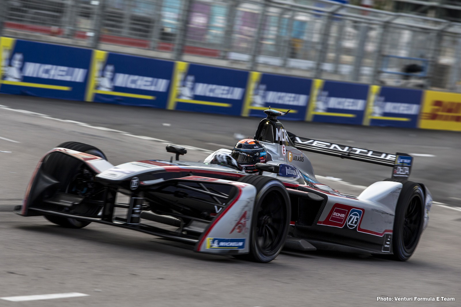
Photo 1. Machine of Venturi Formula E Team
ROHM offers SiC devices to the main inverter as an official technology partner of Venturi Formula E team. In October 2016, the Third Season, the inverter was equipped with a combination of Si-IGBTs (Integrated Gate Bipolar Transistors) with SiC Schottky barrier diodes. In December 2017, the Forth Season, ROHM replaced Si-IGBT with SiC MOSFET, resulting in the higher performance of inverter as smaller, faster, and stronger.
‘Thanks to the new SiC power module, we made a big jump on the inverter side,’ Franck Baldet continued. ‘Because we are always thinking that higher speed motors have a very high efficiency global system package. And in parallel, we were also able to reduce the volume. Reducing it enabled us to put the inverter to the lowest position possible in the car. Why is a lower position important in the car? Because it makes the seed of machine faster. All inputs are coming from the technical regulation. With the new SiC modules we could easily reach the targets for Season 4.’
The Fifth Season will be again very challenging for Venturi Formula E team because in next season they will go up to 220kW. This is a lot of power, a lot of energy, which will be needed as they will only have one car instead of two cars. So they have to double the amount of energy if they have a race that will last up to around 45 minutes. And obviously it´s all about efficiency. Better efficiency, leads to less losses and can be used to bring down the dimensions of the cooling parts. That is the new challenge for the Fifth Season, and they are already testing their new machine. ROHM hopes that our SiC power modules will contribute to their success
The upcoming race in New York will take place as the last e-prix in this season, setting against the iconic backdrop of Lower Manhattan and the Statue of Liberty on July 14 and 15. Looking forward to the last race in the Fourth Season at New York!
For the full interview of Venturi Formula E team, please click here.