Perspective article


[Source] Nikkei Electronics, Sept. 219 Issue, pp published with the permission of Nikkei BP.
ROHM has developed DC/DC converter control technology featuring an ultra-narrow minimum pulse width of 9ns. Referred to as Nano Pulse Control, this technology enables direct conversion from 48V input to around 1V, even at a high switching frequency of 2MHz. By introducing a ‘flying start’ that obtains the coil current required for control in advance, ROHM was able to successfully reduce the minimum pulse width by two-thirds, from the previous 30ns to 9ns. (This article)
Don’t dive into the storm
In response, we began developing technology to reduce the minimum pulse width from 120ns to 20ns. The reason for targeting 20ns was that the narrowest pulse width on the market at the time was 30ns. We wanted to achieve an even narrower pulse width, so set out sights on an unprecedented value of 20ns.
We began development by first sorting out the tasks. Specifically, we organized items into ‘what we are aiming for’ and ‘what we have been doing’. There were two things we were hoping to achieve. One was to detect the coil current with high accuracy and implement feedback control. The other was to reduce the minimum pulse width to 20ns. What we were doing previously was working on reducing noise and circuit delay.
Although focusing on these two methods were certainly not wrong, there were questions regarding whether this was the only way to achieve our goal. So we decided to change our mindset and began thinking of other methods.
Conventionally, since noise is the main issue, we wanted to suppress noise. Also, because this is a problem that occurs when the device is turned ON, it must be solved while turned ON. That is what we believed. One might call this this type of strategy ‘diving into a storm’.
However, we weren’t able to achieve our goals using this method. There was nothing we could do to prevent noise generation. So we decided to give up on facing the issue head-on.
Introducing 'flying start'
If it can’t be solved head-on, how should we approach this issue? Let us consider a hypothetical situation. If you look at the weather forecast for tomorrow and see a 100% chance of rain in the afternoon, you would probably take an umbrella even if it wasn’t raining in the morning. If you know in advance that an event will occur, then you should be able to take measures to deal with it before it happens.
The same can be said for the problem of coil current noise. Since we know in advance that noise will occur, it is a simple matter of detecting the coil current where there is no noise.
There are only 2 candidates for timing the detection of the coil current, before or after noise is generated. Detecting the coil current after is exactly how it was done in the past. So this time we opted for detecting the current before noise is generated (Fig. 7).
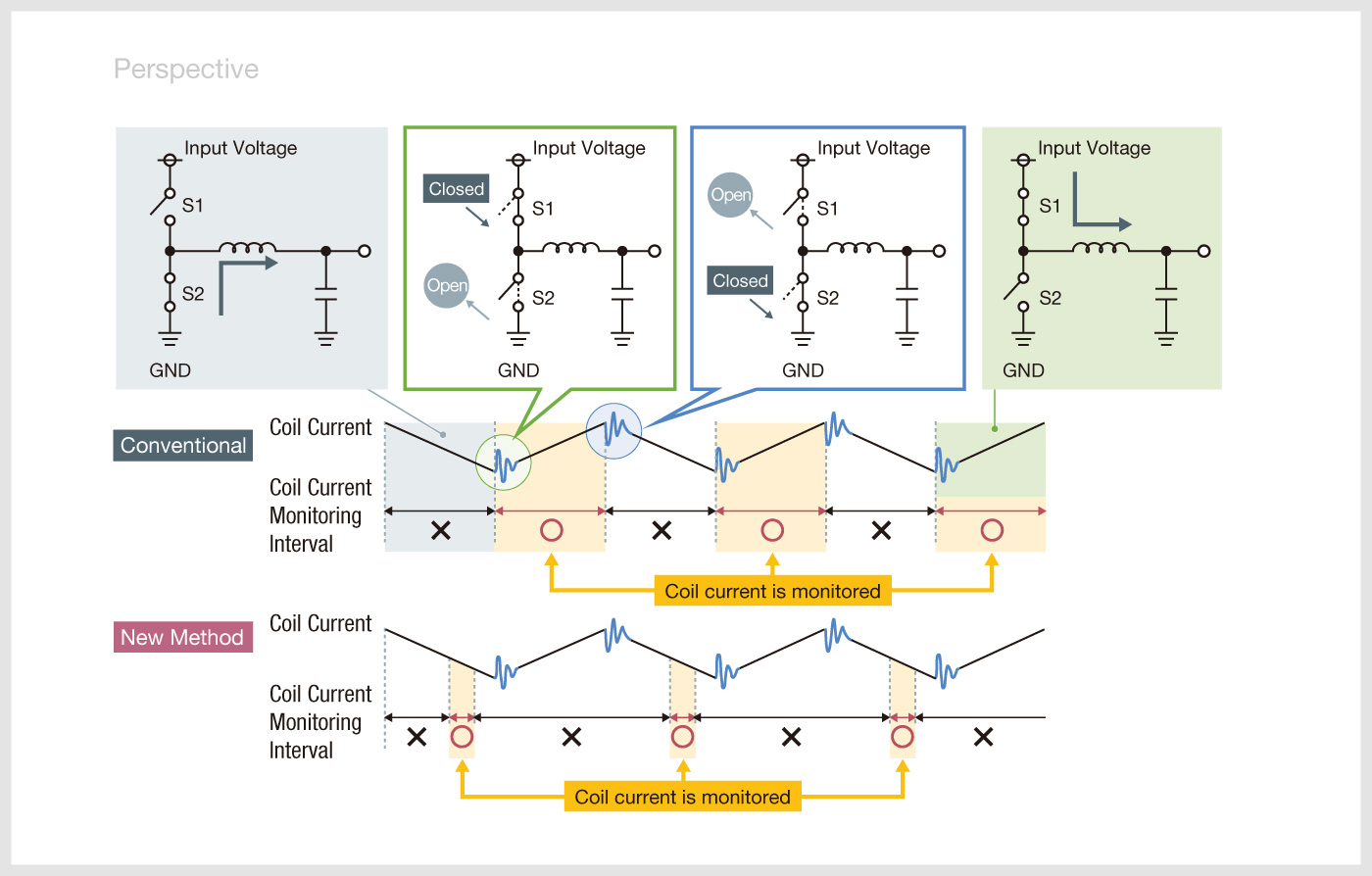
Figure 7. Changing the location for detecting the coil current
ROHM’s Nano Pulse Control technology detects the coil current at a point before noise is generated.
With this method, the process of obtaining information is started before detecting the actual coil current. In other words, we are performing a ‘flying start’. According to our calculations, if we begin to acquire information 30ns before switching ON, even with a conventional circuit delay time of 50ns, the minimum pulse width can be narrowed to -30ns + 50ns = 20ns. This allows us to achieve our goal.
Creating the coil current waveform
The problem here is whether the necessary coil current information can be obtained at a point before noise is generated.
So first, we returned to the starting point of the current mode control method. With current mode control, the coil current information typically required is the change in coil current ΔiL. The effects of output voltage fluctuations due to the increase/decrease in load current appears as a change in the coil current. This change determines the pulse width of the PWM signal.
The coil current waveform is essential for obtaining information on the change in coil current (ΔiL). Two pieces of information are needed to create the optimal waveform. The first is the coil current information when the switch element is turned ON. The second is the rate at which the coil current continues to increase as the switch changes from ON to OFF.
The coil current information at the moment the switch element is turned ON (iL0), as mentioned above, is acquired before noise is generated. After this, if the output voltage fluctuates and coil current changes, the coil current information at the time the switch is turned on (iL0) will increase/decrease. This variation is a function of the change in coil current (ΔiL). Next, depending on the slope of the coil current, a certain physical quantity is detected and substituted into a relational expression developed by ROHM.
In this way, if the coil current information at the moment the switch is turned on (iL0) and the slope of the coil current can be obtained, the waveform of the coil current can be determined. As such, the timing for turning the PWM signal OFF can be can be set by comparing the differential voltage acquired in the first feedback control loop with the voltage value calculated from the coil current waveform in the second feedback control loop of the current mode control method.
However, explaining in this way may cause some to question whether the correct current feedback can be applied using an artificial coil current waveform, created based on previous information before the switch element is turned ON. The answer to these concerns is shown in Fig. 8. This is a Bode diagram of the open loop transfer function of the feedback control loop. A response characteristic of -20dB/dec linear is obtained. As you can see, the current feedback has been properly applied.
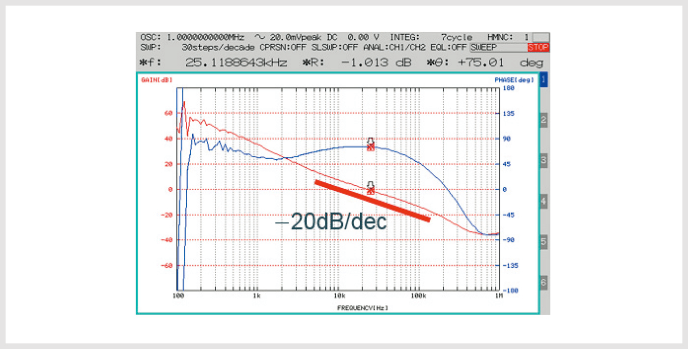
Figure 8. A Bode diagram of the open loop transfer function of the feedback control loop
A linear response characteristic of -20dB/dec was obtained.
Achieving a narrow minimum pulse width of 9 ns
In this way, a flying start is actually possible. In other words, it is possible to obtain the necessary coil current information before noise is generated.
So the question remains, how much of a flying start is possible? It is the length of the OFF period that determines the time. In DC/DC circuits, a certain amount of OFF period is required. So in practice, the flying start begins around 50ns before the switch element is turned ON, and for a period of 30-40ns coil current is stored in the capacitor.
By using these settings we wear able to achieve a minimum pulse width of 9ns, much narrower than our target value of 20ns. We named this technology Nano Pulse Control. At present (July 2019) it is the narrowest minimum pulse width in the industry.
However, in theory it can be made even narrower. Down to around 6ns is possible. But this is difficult to achieve with our current circuit configuration. The reason is that pulse signals require physical time for rising and falling. In other words, 6ns represents the ‘silicon limit’. Nano Pulse Control enables direct conversion from 48V input to around 1V at a high switching frequency of 2.1MHz (Fig. 9). This technology even makes it possible to directly convert 48V to 0.8V.
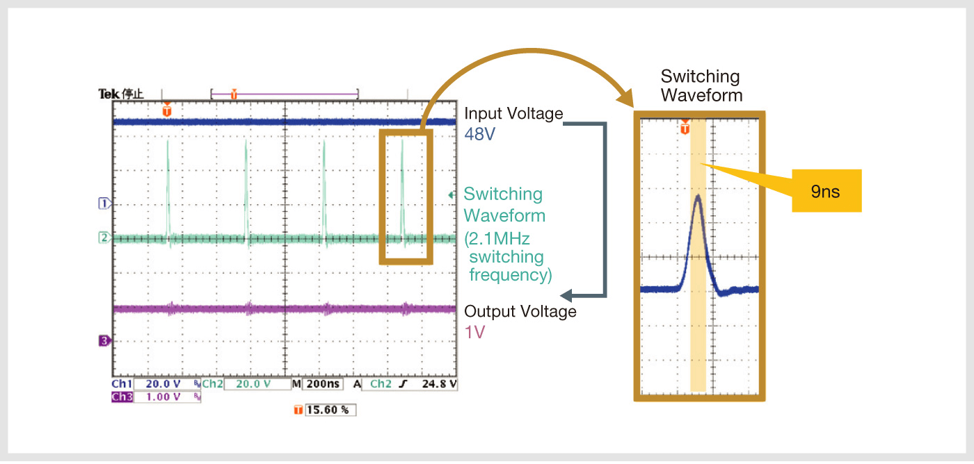
Figure 9. Achieving an extremely narrow pulse width of 9ns
Tests have confirmed that direct conversion from 48V input to 1V output is possible at a high switching frequency of 2.1MHz. The minimum pulse width measured was 9ns.
Related articles