Attention to Internet Explorer users: ROHM website does not recommend browsing in IE 11. Please use latest browser to ensure the best performance on ROHM website.
BTL∗1 output type is designed and evaluated on the assumption that it is used with BTL system. If it is used with SE∗2 output, not only that the electrical characteristics described in the datasheet will not be obtained, but also pop noise may occur due to the absence of a built-in pop noise prevention circuit for SE output. That is why this not recommended.
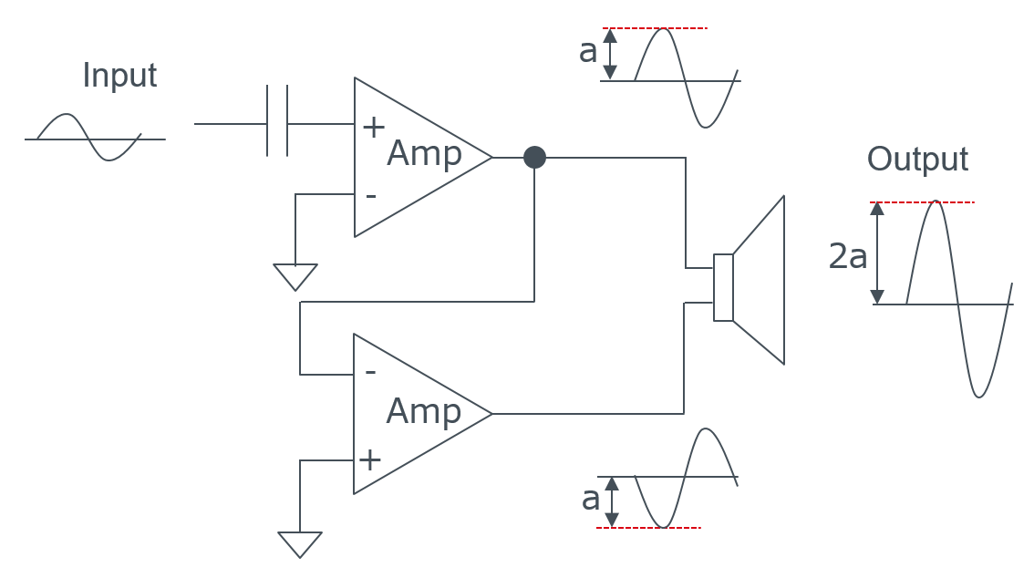
BTL∗1 Abbreviation for Bridged Tied Load, also called Balanced Transformer Less. By bridging the outputs of the two amplifiers and connecting them to the loudspeaker, the output voltage is doubled and the output power is quadrupled compared to the SE output type.
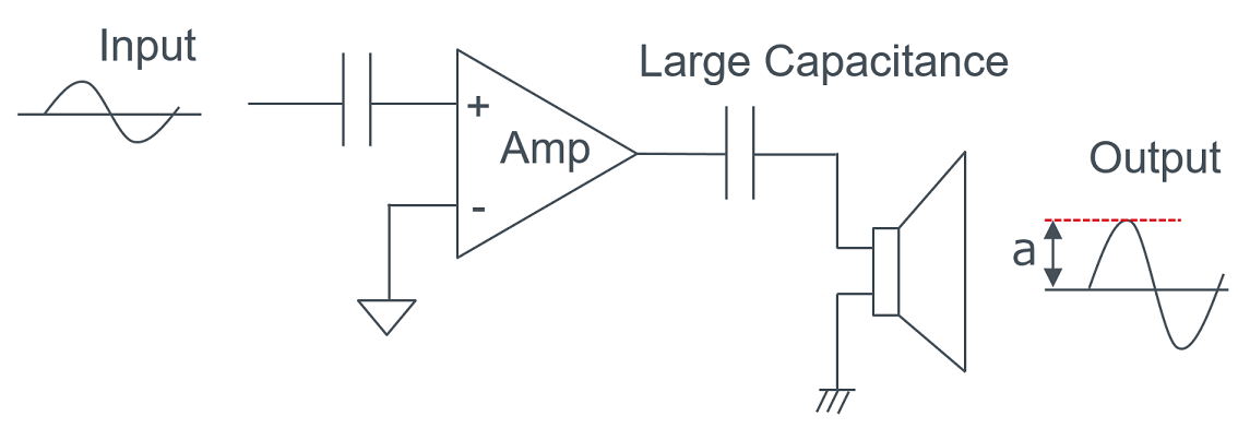
SE∗2 Abbreviation for Single Ended. A method in which a Speaker is connected between the Speaker Amplifier output and GND. Since the Speaker Amplifier output is biased by half (1/2) of the Power Supply Voltage, a coupling capacitor must be placed between the Speaker Amplifier output and the Speaker to prevent DC current from flowing through the Speaker. Since the load resistance of the Speaker is generally low (4~8Ω), a large coupling capacitor of about 1000µF is needed to pass low frequency range.
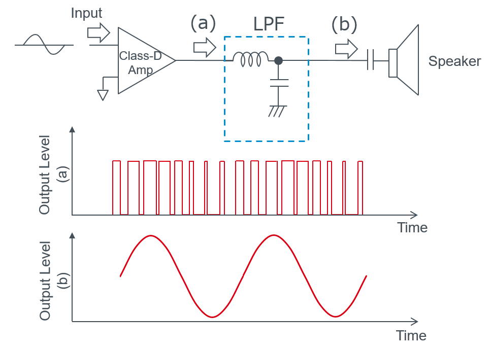
Class-AB Speaker Amplifiers, also called Linear Amplifiers, are Speaker Amplifiers that amplify the input signal as it is to drive the speaker. Generally, this method has an efficiency of less than 50% and generates a lot of heat. Class-D Speaker Amplifiers, also called Digital Amplifiers, are Speaker Amplifiers that convert (analog) input signals into pulses as output. This method achieves high efficiency and low power consumption by converting the output into PWM∗1 pulses.
PWM∗1 Abbreviation for Pulse Width Modulation. In the case of a class-D Speaker Amplifier, an LPF (low-pass filter) is attached to the output so that the carrier signal is removed and the audio signal can be extracted.
Class-D Speaker Amplifiers have higher efficiency and lower power consumption than that of Class-AB Speaker Amplifiers, resulting in less heat generation. However Class-D Speaker Amplifiers have the disadvantage of requiring more external components because an LC filter is generally inserted at the output terminal to eliminate the carrier frequency of PWM. For small output Speaker Amplifiers of around 2 W, it is recommended to use class-D Speaker Amplifier if low power consumption is important. On the otherhand, if reduction of external components is important then class-AB Speaker Amplifier is recommended. For Speaker Amplifiers with medium or higher output power, such as those with output power exceeding 5 W, the Class-AB Speaker Amplifiers may require a heat sink for heat dissipation, which may not reduce the mounting area. Also, since Class-AB Speaker Amplifiers with a linear drive system have better EMI∗1 characteristics than Class-D amplifiers with a pulse drive system, this point should also be taken into consideration when making a selection.
EMI∗1 Abbreviation for Electro Magnetic Interference. Electromagnetic interference is when radio waves or high-frequency electromagnetic waves affect electronic equipment as noise. EMC is also referred to as Electro Magnetic Susceptibility (EMS), which is the ability not to be disturbed by electromagnetic interference.
To measure the distortion factor, the PWM output signal must be converted to an analog signal. Add a low-pass filter (LC filter) in series with the output of the class-D Speaker Amplifier and convert it to an analog signal. For the constants of the low-pass filter (LC filter), please refer to the datasheet. When using Audio Precision's Audio Analyzer, input the analog signal converted by AUX-0025 to the Audio Analyzer to measure the distortion factor.
When a Pull-Up resistor is connected to the GAIN pin, the voltage at the GAIN pin is divided by the Pull-Up resistor connected to the pin and the built-in 33kΩ Pull-Down resistor. If you connect a Pull-Up resistor, please make sure that the resistor value is small enough to meet the specified value of H-level input voltage.
BD5423AEFS for analog input type and BD28623MUV for digital input type can be used as a monaural amplifier by stopping one channel. For circuit configuration, refer to p.12 of the application manual (contact us separately) for BD5423AEFS, and p.39 of the data sheet for BD28623MUV.
Although it is not possible to stop 1 unused channel, it can be used as a monaural amplifier by connecting each terminal of the unused channel as follows: Connect the power supply and GND in the same way as for the unused channel. Connect decoupling capacitors. Connect unused input pins to GND via coupling capacitors. Unused output pins can be left open, but we recommend connecting an LC filter for EMI protection. Connect a BSP capacitor.
The withstand voltage should be at least twice the supply voltage used. It is also recommended to use components with good DC voltage application characteristics and temperature characteristics.
When an output stage feedback circuit is present, power supply voltage fluctuations are suppressed by the feedback circuit and have little effect on the output PWM signal waveform, so power supply fluctuations are not output as noise from the speaker. If there is no output stage feedback circuit, fluctuations in power supply voltage affect the waveform of the output PWM signal and may be output from the speaker as noise.