Rohm Breadcrumb

Damage to thick-film resistors due to surges(r_what10)
Chip Resistor Failure Modes
Damage to Thick-Film Resistors Due to Surges
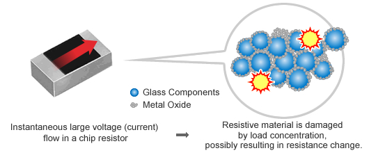
Surges are large voltages or currents instantaneously applied to circuits. Well-known examples include lightning and static electricity.
Surge voltage applied to a resistor may affect the resistance characteristics due to excessive electrical stress or result in damage (worst-case scenario).
Increasing Surge Resistance
One method for improving surge resistance is explained below.
- Utilize materials with strong surge resistance
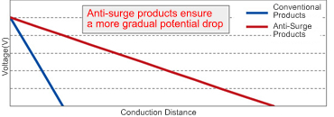
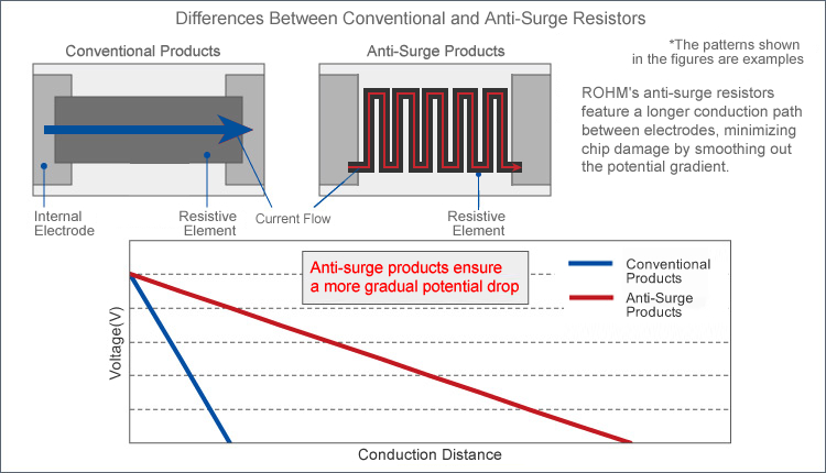
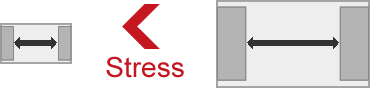
- Increase the distance between electrodes, minimizing chip damage due to a smoother potential gradient.
Increasing the chip size will lengthen the distance between electrodes and provide greater surge resistance, but requires a larger mounting area.
For Sets With Insufficient Board Space Requiring Further Miniaturization but Need to Protect Against Surges
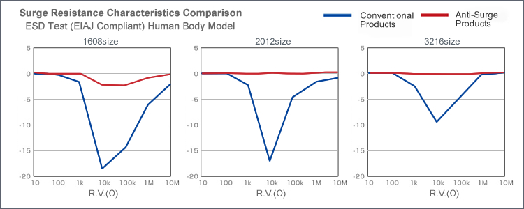
Anti-surge chip resistors provide superior surge resistance in a compact size.
ESD Test (EIAJ Compliant) Human Body Model
| Type | Size | Guaranteed Surge Resistance Value |
|---|---|---|
| ESR01 | 1005mm (0402inch) |
2kV |
| ESR03 | 1608mm (0603inch) |
3kV |
| ESR10 | 2012mm (0805inch) |
3kV |
| ESR18 | 3216mm (1206inch) |
3kV |
| ESR25 | 3225mm (1210inch) |
5kV |
| LTR10 | 2012mm (0805inch) |
3kV |
| LTR18 | 3216 (1206inch) |
3kV |
| LTR50 | 5025mm (2010inch) |
3kV |
| LTR100 | 6432mm (2512inch) |
3kV |
ROHM Anti-Surge Chip Resistors:
- Utilize materials that provide superior surge resistance
- Adopt a proprietary resistive element design that minimizes damage to the chip by providing a smooth potential gradient
ROHM's anti-surge chip resistors feature improved the power handling characteristics and a revised element shape to achieve higher rated power than conventional types.
| Size | ESR Series | MCR Series |
|---|---|---|
| 1005 | 0.2W | 0.063W |
| 1608 | 0.25W | 0.1W |
| 2012 | 0.4W | 0.125W |
| 3216 | 0.33W | 0.25W |
| 3225 | 0.5W | 0.25W |
| 5025 | - | 0.5W |
ROHM's ESR and LTR series provide improved surge-resistance characteristics and higher rated power while maintaining size.
Lineup
| Part No. | Size | Rated Power (70℃) |
Maximum Element Voltage(V) |
Resistance Tolerance |
Temperature Coefficient of Resistance (ppm/℃) |
Resistance Range | Operating Temp. Range(℃) | Automotive Qualified (AEC-Q200) |
|---|---|---|---|---|---|---|---|---|
| SDRSeries | ||||||||
| NewSDR03 | 1608 | 1/4W (0.25W) |
150 | J(±5%) | ±200 | 1~10MΩ(E24Series) | -55~ +155 |
Yes |
| F(±1%) | ±200 ±100 |
1~9.76Ω(E24,96Series) 10~10MΩ(E24,96Series) |
||||||
| D(±0.5%) | ±100 | 10~1MΩ(E24,96Series) | ||||||
| ESRSeries | ||||||||
| ESR01 | 1005 | 1/5W (0.2W) |
50 | J(±5%) | +500/-250 ±200 |
1Ω~9.1Ω(E24Series) 10Ω~10MΩ(E24Series) |
-55~ +155 |
Yes |
| F(±1%) | ±100 | 10Ω~976kΩ(E24,96Series) 1MΩ~2.2MΩ(E24Series) |
||||||
| ESR03 | 1608 | 1/4W (0.25W) |
150 | J(±5%) | ±200 | 1Ω~10MΩ(E24Series) | Yes | |
| F(±1%) | ±200 ±100 |
1Ω~9.76Ω(E24,96Series) 10Ω~10MΩ(E24,96Series) |
||||||
| D(±0.5%) | ±100 | 10Ω~1MΩ(E24,96Series) | ||||||
| ESR10 | 2012 | 2/5W (0.4W) |
150 | J(±5%) | ±200 | 1Ω~30MΩ(E24Series) | Yes | |
| F(±1%) | ±100 | 1Ω~10MΩ(E24,96Series) | ||||||
| D(±0.5%) | ±100 | 10Ω~1MΩ(E24,96Series) | ||||||
| ESR18 | 3216 | 1/3W*1 (0.33W) |
200 | J(±5%) | ±200 | 1Ω~15MΩ(E24Series) | Yes | |
| F(±1%) | ±100 | 1Ω~10MΩ(E24,96Series) | ||||||
| D(±0.5%) | ±100 | 10Ω~1MΩ(E24,96Series) | ||||||
| ESR25 | 3225 | 1/2W*1 (0.5W) |
200 | J(±5%) | ±200 | 1Ω~10MΩ(E24Series) | Yes | |
| F(±1%) | ±100 | 1Ω~10MΩ(E24,96Series) | ||||||
| D(±0.5%) | ±100 | 10Ω~1MΩ(E24,96Series) | ||||||
| LTRSeries | ||||||||
| LTR10 | 2012 | 1/4W (0.25W) |
150 | J(±5%) | ±200 | 1Ω~1MΩ (E24Series) | -55~ +155 |
Yes |
| F(±1%) | ±100 | 1Ω~1MΩ(E24,96Series) | ||||||
| D(±0.5%) | ±100 | 10Ω~1MΩ(E24,96Series) | ||||||
| LTR18 | 3216 | 3/4W (0.75W) |
200 | J(±5%) | ±200 | 1Ω~1MΩ(E24Series) | Yes | |
| F(±1%) | ±100 | 1Ω~1MΩ(E24,96Series) | ||||||
| D(±0.5%) | ±100 | 10Ω~1MΩ(E24,96Series) | ||||||
| LTR50 | 5025 | 1W | 200 | J(±5%) | ±200 | 1Ω~1MΩ(E24Series) | Yes | |
| F(±1%) | ±100 | 1Ω~1MΩ (E24,96Series) | ||||||
| D(±0.5%) | ±100 | 10Ω~1MΩ(E24,96Series) | ||||||
| LTR100 | 6432 | 2W | 200 | J(±5%) | ±200 | 1Ω~1MΩ(E24Series) | Yes | |
| F(±1%) | ±100 | 1Ω~1MΩ (E24,96Series) | ||||||
| D(±0.5%) | ±100 | 10Ω~1MΩ(E24,96Series) | ||||||
※E24:Standard Products/ E96:Custom Order Products
※Please contact a ROHM representative regarding commercial-grade products
High Reliability ResistorsDownload datasheet
Resistance Failure Due to Solder Cracks
Why Do Solder Cracks Occur?
Chip resistors are mounted on boards using solder, enabling use under a variety of environments. Operation at both high temperatures (>100°C) and low temperatures (<-40°C) are also possible.
A difference in the degree of contraction (thermal expansion coefficient) due to temperature between the alumina substrate (used as a base in thick-film resistors) and FR-4 glass epoxy resin (typically adopted in mounting boards).This difference can result in excessive stress during repeated temperature cycling, leading to cracking at the solder fillet at the junction between the materials.

| Material | Thermal Expansion Coefficient (10-6/℃) |
|---|---|
| Alumina | 7.1 |
| FR-4 (Glass Epoxy Resin) |
14 |
※Highlighted for the image
※Photo of thick-film resistor
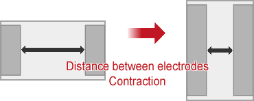
Because of stress generated due to chip contraction, a longer distance between electrodes or larger chip size is considered disadvantageous.
Preventing Solder Cracks
Solder Cracks can be Prevented by Shortening The Distance Between Electrodes or Reducing Chip Size. However, there is often a tradeoff relationship between electrical characteristics such as chip size, rated power, and maximum element voltage.
Typically, characteristic values tend to decrease as products become smaller.

Improve Junction Reliability
Some Users Seek to improve junction reliability in order to prevent solder cracks without compromising specifications such as rated power, or would like to increase rated power by increasing chip size without reducing junction reliability.
In contrast, wide-terminal types reduce the distance between electrodes while maintaining size.
Solder cracks did not occur during actual temperature cycling tests.
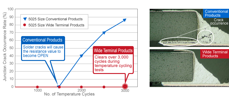
Test Conditions:
JIS C 5201-1 sec4.9 compliance
Condition: -40℃:
30min / +125℃: 30min
Air Layer 3000 cyc
Test Board:
FR-4
Solder:
Sn/3.0Ag/0.5Cu ( t = 0.100mm)
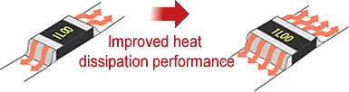
Adopting a wide terminal structure lengthens the heat dissipation pathway, improving rated power.
| Size | LTR series | MCR series |
|---|---|---|
| 2012mm [0805inch] |
0.25W | 0.125W |
| 3216mm [1206inch] |
0.75W | 0.25W |
| 5025mm [2010inch] |
1W | 0.5W |
| 6432mm [2512inch] |
2W | 1W |
Utilizing the wide-terminal LTR series will make it possible to prevent solder cracks and increase the rated power. In addition, high surge resistance is achieved, providing improved reliability.
Lineup
| Part No. | Size | Rated Power (70℃) |
Maximum Element Voltage(V) |
Resistance Tolerance |
Temperature Coefficient of Resistance (ppm/℃) |
Resistance Range | Operating Temp. Range(℃) | Automotive Qualified (AEC-Q200) |
|---|---|---|---|---|---|---|---|---|
| LTR10 | 2012 | 1/4W (0.25W) |
150 | J(±5%) | ±200 | 1Ω~1MΩ (E24 Series) | -55~ +155 |
Yes |
| F(±1%) | ±100 | 1Ω~1MΩ(E24,96 Series) | ||||||
| D(±0.5%) | ±100 | 10Ω~1MΩ(E24,96 Series) | ||||||
| LTR18 | 3216 | 3/4W (0.75W) |
200 | J(±5%) | ±200 | 1Ω~1MΩ(E24 Series) | Yes | |
| F(±1%) | ±100 | 1Ω~1MΩ(E24,96 Series) | ||||||
| D(±0.5%) | ±100 | 10Ω~1MΩ(E24,96 Series) | ||||||
| LTR50 | 5025 | 1W | 200 | J(±5%) | ±200 | 1Ω~1MΩ(E24 Series) | Yes | |
| F(±1%) | ±100 | 1Ω~1MΩ (E24,96 Series) | ||||||
| D(±0.5%) | ±100 | 10Ω~1MΩ(E24,96 Series) | ||||||
| LTR100 | 6432 | 2W | 200 | J(±5%) | ±200 | 1Ω~1MΩ(E24 Series) | Yes | |
| F(±1%) | ±100 | 1Ω~1MΩ (E24,96 Series) | ||||||
| D(±0.5%) | ±100 | 10Ω~1MΩ(E24,96 Series) |
*1 Please contact a ROHM representative regarding high power products.
※E24:Standard product/ E96:Custom order product
Wide Terminal Type High Power Chip ResistorsDownload datasheet
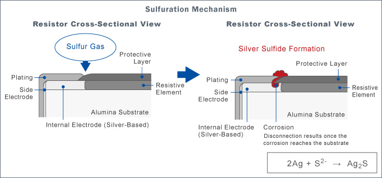
Resistor Sulfuration
Sulfur components exist in a variety of forms in the atmosphere, such as in vehicle exhaust gases and gases emitted from hot springs. These components are adsorbed by metal surfaces, where they will gradually react.
In thick-film chip resistors, sulfur gas in the air can be introduced in the gap between the protective layer and plating, gradually reacting with the internal silver (Ag) electrode to form silver sulfide (Ag2S). (See figure below.) This will cause the internal electrodes to become disconnected, resulting in failure. This failure mode is referred to as disconnection due to sulfide.

Tolerance for Sulfurization Chip ResistorsDownload datasheet
electronics_tips_menu