di_what1
What is a Diode?
<Diode Fundamentals and History>
Tale of a Diode
Below we have compiled some of the history and principles behind diodes. If you feel it's necessary, give it a glance to refresh your memory. "Well I already knew that!" is what some of you are thinking, and if that is the case, feel free to skip this section. Before we get into some of the properties and fundamentals of diodes, let's talk about the Edison effect.
The Edison effect happens when electrons would flow from a heated element to a cooler metal plate, in a vacuum. When Edison discovered this, he didn't really see a use for it, but went ahead and patented it anyway. Edison patented everything in sight. The more descriptive term, "thermionic emission" is used to describe this effect today.
Now the Edison effect has an interesting feature. The electrons can flow only one way. Only from the hot element to the cool plate, never the opposite way. A good comparison would be water flowing through a check valve. We call devices that allow electricity to flow only one direction, diodes.
Before the Vacuum Tube
Rectifying properties and the Edison effect were discovered in the two-pole vacuum tube in 1884. Eight years before that, the rectifying effect of selenium was discovered in 1876. The history of using properties of semiconductors to create diodes that possess rectifying effects is very old. It may be hard to believe, but the history of semiconductors dates back before that of the vacuum tube!
From Germanium to Silicon
The first primitive diodes, like the selenium rectifier or crystal detectors, used iron pyrites and galena as well as other natural copper oxides (polycrystalline semiconductors). As refining techniques advanced, we entered the age where highly sensitive single crystalline semiconductors could be produced with reliability. The age of germanium and silicon. During this time, we learned that germanium has a low resistance to heat, and so in today's world, most semiconductors are made with silicon.
Rectification From the PN Junction
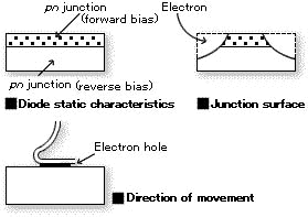
The diode element consists of a structure called the pn junction. The terminal attached to the p-type semiconductor is called the anode, and the terminal attached to the n-type semiconductor is called the cathode. Current is allowed to flow from the anode to the cathode, but almost completely prevented from flowing in the reverse direction. This phenomenon is called rectification, and, put simply, it converts alternating current to a unidirectional current.
Diode model


Diode schematic electrical symbol

In Other Words, a Diode is a Valve!
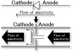
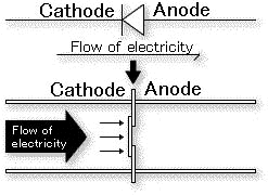
As previously mentioned, if you were to think of an image that exemplifies the effects of a diode, you might think of it as a "valve" for electrical current. If you think of electrical current as flowing water, the anode could be considered the upstream side and the cathode the downstream side. Water flows from upstream to downstream (or shall I say, the electrical current does), but the "valve" prevents it from flowing from downstream to upstream. This is the principle operation of a diode.

●The valve is open and electricity flows
(forward direction)

●The valve is closed and electricity does not flow
(reverse direction)
The Many Types of Junctions
Today's diodes can be divided into two main classifications via junction: the pn junction and the Schottky barrier junction. The first one is a semiconductor-to-semiconductor junction, and this type of junction can be further classified into diffusion type junctions and mesa type junctions. The latter one uses the effects caused between a semiconductor and a metal, and isn't actually a junction in terms of diodes.
However, to make things easier to understand, it will be considered a junction here. Currently, the Schottky barrier diode is known for its low power requirements and high speeds, and ROHM is making great advances with its Schottky barrier diode series.
Forward bias characteristics and reverse bias characteristics

A diode has two electrodes: the anode and the cathode. The anode is the (+) terminal and the cathode is the (-) terminal. The characteristics of the diode when current is flowing from the anode to the cathode are called the forward bias characteristics and VF and IF are examples of these characteristics. Conversely, if a (-) voltage is applied to the anode and a (+) voltage is applied to the cathode, current is prevented from flowing through the diode. The characteristics at this time are called the reverse bias characteristics and VR and IR are examples of these characteristics.
electronics_tips_menu


