Attention to Internet Explorer users: ROHM website does not recommend browsing in IE 11. Please use latest browser to ensure the best performance on ROHM website.
A photointerrupter is transmission-type photosensor that integrates optical receiving and transmitting elements in a single package. Since the method involves light blocking ROHM calls this device a photointerrupter. A long life GaAs infrared photodiode is utilized for output while a single phototransistor and photo IC are integrated for light detection.
•ROHM photointerrupters are available in two types: insertion and dual mold (refer to Fig. 1). Insertion-type products are general-purpose units featuring injection mold processing that integrate both optical transmitting and receiving elements. •Dual mold photointerrupters are generally more compact than their insertion-type counterparts. They feature mold resin construction and utilize higher efficiency transmitters/receivers. However, the epoxy resin is relatively weak compared with that of transistors and ICs with respect to temperature resistance, resistance to solvents, and mechanical resistance. Therefore, please take this into account during mounting and when handling.
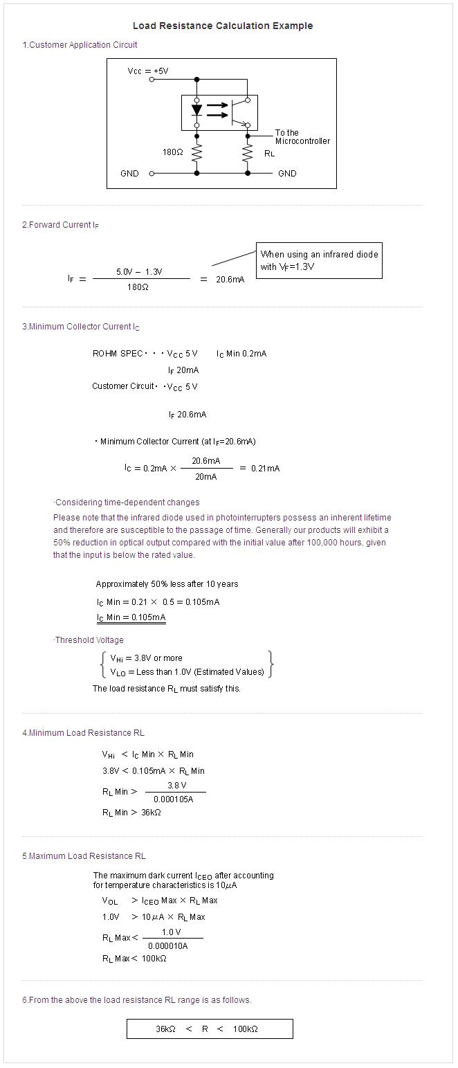
Please refer to the next item during circuit design. A ·The operating current of the infrared diode will differ based on the application, making it necessary to select the appropriate load resistance for the phototransistor. If the proper load resistance is not used the circuit will not operate.
·Simulation using the upper and lower limits of the emission strength. A value roughly between the maximum dark current and threshold voltage exists.
B Please note that when using 2 or more in series the resistance of the infrared diodes will become common and differences in VF may result in abnormal operation. Please refer to the calculations below
Please consider the following items during the lead forming stage. 1.When forming the lead please avoid making the base part a fulcrum and ensure that the pin is not fixed 2.Bend the pin at least 2mm from the base 3.Perform lead forming before soldering 4.Do not bend the lead at the same location multiple times
Please refer to the following recommendations regarding mounting Please ensure that the lead pitch matches the pitch of the through-holes on the board and is not too wide or narrow. When using a holder, please consider the dimensions and tolerances of the holder, board, and part in order to prevent applying undue stress to the leads.
Note:Please consider the thermal expansion coefficients of the materials used. Stress may be applied to the pins due to expansion and contraction of the holder during preheating and soldering, which can lead to breakage.
The recommended soldering conditions are given below.
* Use rosin-based flux only. Note that strongly acid or alkaline flux may cause corrosion. * The surface mount devices reguire special attention. Please check requested time control after opening sealed bug, land pattern, the thickness of solder paste screen etc.
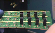
Please take the following into consideration during board design ·The case insertion type is weaker against bending and mechanical stress than the dual mold type. Therefore, please do not separate by hand after soldering (see photos below) and when using a jig or other type of holder ensure that no stress is applied.
·After soldering do not twist the insertion type with force (greater than 100g), as doing so will cause breakage.
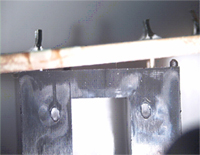
Please refer to the following recommended precautions Using too much torque when installing the above-mentioned type can cause the part to short-circuit with the chassis. Therefore, please refer to the following recommendations. 1.Screw: M1.4 ø2.5mm (plastic) 2.Torque:0.049 to 0.078N·m (do not over-torque) 3.Please screw in from the phototransistor side 4.Chassis:Please ensure that GND is not shorted to VCC
The response speed of the photointerrupter must be taken into account during high-speed switching operations. Please ensure that sufficient margin exists when using ON/OFF control elements operating in the usec order. Also, reduce the resistance at the phototransistor side during high-speed operation, as well as the resistance in the infrared block, for greater current flow. Another consideration is the amount of light blocked by the light shield. Set the light shield/aperture to 3-10%.