Rohm Breadcrumb

memory_what7
EEPROM I/F Features
Interface Selection
Generally, serial EEPROMs utilize 3 types of interfaces - Microwire, SPI, and I2C. Each provides distinct advantages. Users should select the ideal interface based on application requirements.
I2C
There is a limit to the number of MCU ports that can be used. When seeking to minimize the number of ports used for EEPROM I/F, I2C, which requires only 2 lines for MCU control, is recommended. Multiple EEPROMs can be connected on the same bus without adding ports, making I2C ideal when utilizing more than one EEPROM in the same set.
One drawback, however, is the relatively slow communication rate (400K to 1Mb/s). This limits the access time, rendering it unsuitable for high-speed applications.
Benefits:
- Enables communication using only 2 wires, reducing the number of MCU ports required.
- Multiple EEPROMs can be connected to the same bus
SPI
For high-speed communication, SPI, which is capable of speeds up to 20Mb/s, is the preferred choice. Because higher speeds are possible, EEPROMs with capacities as much as 1Mbit are offered. However, SPI requires 4 wires for communication, double the amount of I2C.
Benefits:
- High operating frequency enables high communication rate
- Broad capacity range
Microwire
This older communication method is slower than SPI and is only available in smaller capacities. Also, like SPI, 4 wires are needed - twice as much as I2C.
Benefits:
- Slower communication speeds than SPI
- Available only in smaller (memory) capacities
Pin Layout and Functions
I2C
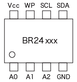
| Pin Name | Input/Output | Function |
|---|---|---|
| SCL | Input | Serial Clock Input |
| SDA | Input/Output | Serial Clock Input / Output |
- Controls the EEPROM using 2 lines
- Slave addresses can be set at each pin (A0, A1, A2).
- This allows up to 8 EEPROMs to be connected on the same bus.
SPI
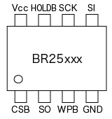
| Pin Name | Input/Output | Function |
|---|---|---|
| CSB | Input | Chip Select Input |
| SCK | Input | Serial Clock Input |
| SI | Input | Serial Data Input |
| SO | Output | Serial Data Output |
- Controls the EEPROM using 4 lines.
- HOLDB pin makes it possible to serial communication.
Microwire
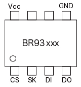
| Pin Name | Input/Output | Function |
|---|---|---|
| CSB | Input | Chip Select Input |
| SK | Input | Serial Clock Input |
| DI | Input | Serial Data Input |
| DO | Output | Serial Data Output |
- Controls the EEPROM using 4 lines
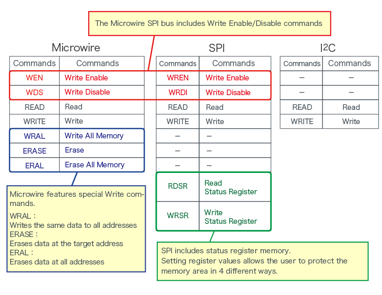
Command Comparison
Application Example: Configuring Multiple EEPROMs (I2C)
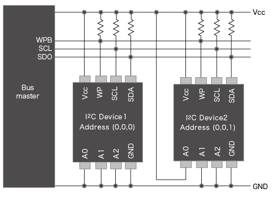
Multiple EEPROMs can be used by simply changing the device address settings (A0, A1, A2) for each IC.
Example:
- Device1:(0,0,0)
- Device2:(0,0,1)
Selecting the target device is performed by entering the device address via serial signal from the Bus Master.
Application Example: Configuring Multiple EEPROMs (Microwire)
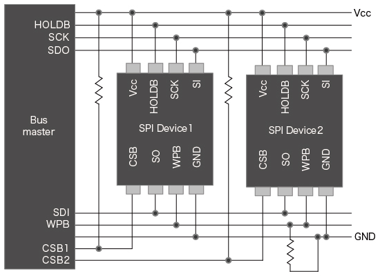
Each EEPROM is individually controlled by the Bus Master via the CS pin. This allows other communication lines to be shared and enables each device to be independently accessed.
electronics_tips_menu