Attention to Internet Explorer users: ROHM website does not recommend browsing in IE 11. Please use latest browser to ensure the best performance on ROHM website.
With the ability to store electrical charge, block DC signals, and pass AC signals capacitors are play a pivotal role in electronic circuits. As such they are used for backup (battery), decoupling (reduce noise), and coupling (remove DC bias voltage). At type of passive component like resistors and inductors (coils), capacitors are used in everything from smartphones, wearables, and data centers to base stations, industrial equipment, and automotive systems. Although the term capacitor is common in most parts of the world, in Japan it's often referred to as a condenser.
Structures and Features of Different Capacitors
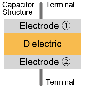
Capacitors come in various types, but the basic structure consists of an insulator (dielectric) sandwiched between electrodes, capable of storing charge when a voltage is applied. Actual products include single-layer, trench, multilayer, electrolytic, and wound types. Capacitors can be differentiated by the following characteristics depending on the dielectric and electrode materials used. Polarity, small/large size, thin/low-profile, operating temperature range, capacitance size, rated voltage range, high-frequency performance, capacitance stability, presence/absence of noise due to piezoelectric effects, etc. Therefore, when selecting a capacitor, it is necessary to understand the characteristics of each type.
[Types and Characteristics of Different Capacitors】
*Scroll horizontally
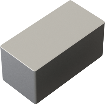
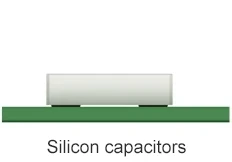
Silicon Capacitor
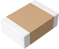
Multilayer Ceramic Capacitor
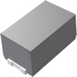
Tantalum Capacitor
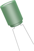
Aluminum Electrolytic Capacitor
Capacitor Appearance
Electrode ①
Doped silicon
Nickel
Tantalum (anode)
Aluminum (anode)
Dielectric
Silicon oxide or Silicon nitride
Temperature compensating ceramic
High dielectric constant ceramic
Tantalum pentoxide
Aluminum oxide
Electrode ②
Doped silicon
Nickel
Manganese dioxide (cathode)
Conductive polymer (cathode)
Electrolyte (cathode)
Conductive polymer (cathode)
Polarity
No
No
Yes
Yes
Compact
◎
◎
◎
〇
〇
×
×
Thin/Low Profile
◎
〇
〇
△
△
×
×
Operating Temperature Range
◎
〇
〇
〇
〇
△
〇
Large Capacitance
△
×
〇
〇
〇
◎
◎
High Rated Voltage
〇
◎
◎
〇
〇
◎
△
High Insulation Resistance (Low Leakage Current)
◎
◎
◎
〇
△
〇
△
High Frequency Characteristics
◎
〇
〇
×
△
×
△
Capacitance Stability
DC Bias
◎
◎
×
◎
◎
◎
◎
Temperature
◎
◎
×
〇
〇
×
〇
High Reliability
◎
〇
〇
×
△
×
△
Noise (Ringing)
No
Yes
No
No
Advantages
Compact
Low profile
Good high frequency characteristics
High operating temp
High capacitance stability
High Reliability
High EMI immunity(can include TVS protection element)
No noise since no piezoelectric effects
Compact
Good high frequency characteristics
High capacitance stability
Compact
Good high frequency characteristics
Large capacitance in a compact size
High capacitance stability
Large capacitance in a compact size
High capacitance stability
Lower ESR and higher allowable ripple current than manganese dioxide products
Large capacitances
Broad lineup
Large capacitances
High capacitance stability
Lower ESR and higher allowable ripple current than electrolytic products
Disadvantages
Small capacitances
Limited lineup
Small capacitances
Ringing noise generated due to piezoelectric effect
Prone to cracking during substrate partitioning and temperature changes
Low capacitance stability
Ringing noise generated due to piezoelectric effect
Prone to cracking during substrate partitioning and temperature changes
Failure in short mode
Polarized
Failure in short mode
Polarized
Large product size
Short lifespan due to liquid leakage
Polarized
Large product size
Polarized
◎: Excellent 〇: Very Good △: Average ×: Poor
About Capacitance
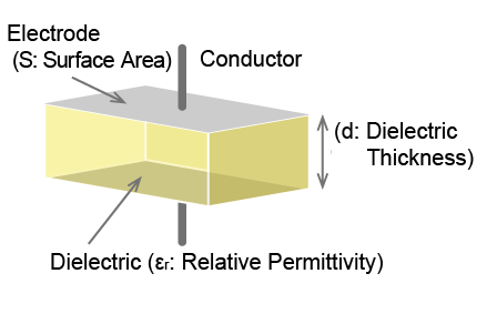
Capacitance is a typical characteristic of a capacitor. And is generally expressed by the following formula. Capacitance=εr×ε0×S/d (εr:Relative permittivity of the dielectric, ε0:Permittivity of a vacuum =8.9×10⁻¹²[F/m], S:Electrode surface area, d:Dielectric thickness)
As the above equation shows, capacitance is proportional to the surface area of the electrode and dielectric constant of the dielectric and inversely proportional to the dielectric thickness. Relative permittivity is an inherent value of the dielectric material used. The unit of capacitance is F (farad), and in practice pF (picofarad), nF (nanofarad), uF (microfarad), mF (millifarad), etc. are commonly used. ( 10-12[F]=1pF, 10-9[F]=1nF, 10-6[F]=1[μF], 10-3[F]=1[mF] )
Capacitor Applications
Capacitors (including tantalum) are often used in the following applications.
Backup (Battery)
Utilizing as a battery
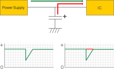
When the load current increases due to power supply interruption or a sudden rise in IC drive speed, the line voltage from the power supply may drop, possibly causing IC malfunction. To prevent this, charge stored in a capacitor is supplied to the IC, temporarily maintaining the line voltage.
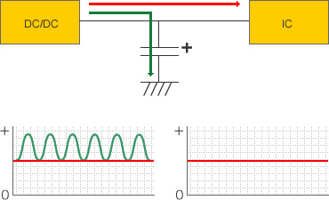
Decoupling
Utilizing AC characteristics
To supply stable DC voltage, capacitors are used to remove high-frequency noise caused by high-speed circuit drive or externally induced noise superimposed on the power supply line. Adopted in general power supply circuits.
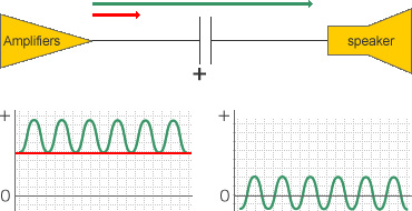
Coupling
In this application, the capacitor removes the DC bias voltage from the previous stage and only passes through the AC signal voltage.
Typically adopted in audio circuits.
Silicon Capacitor Outline
Featuring a compact, low-profile factor, silicon capacitors utilize thin-film semiconductor technology to provide stable capacitance in response to applied voltage and temperature changes.
What’s more, as there is no piezoelectric effect, no audible noise is generated due to voltage fluctuations.
ROHM also offers products with built-in TVS protection elements that ensure high ESD tolerance.
Silicon capacitors with these features are used in everything from smartphones, wearable devices, and high-speed large-capacity communication applications to automotive systems and industrial equipment.
Classification Based on Internal Structure and Mounting Method
1.Classification by Internal Structure
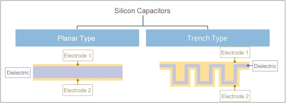
The internal structure of silicon capacitors can be divided into two types: planar and trench.
Planar types have a simple shape that is easy to produce, making them suitable for high-voltage applications due to their uniform dielectric and electrodes.
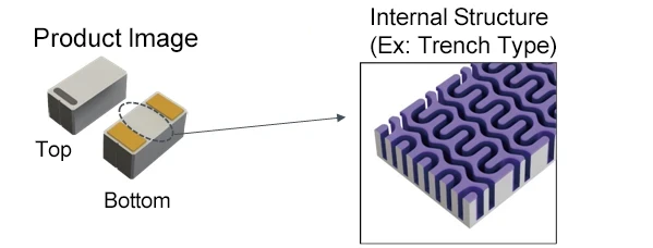
Trench types feature a larger electrode and dielectric surface area by forming trenches (grooves) in the substrate. As a result, larger capacitances can be achieved over planar types.
ROHM focuses on compact, large capacitance trench-type products.
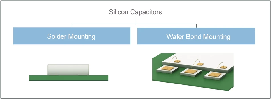
2.Classification Based on Mounting Method
Two mounting methods for silicon capacitors exist: solder and wire bond.
Solder mounting is suitable for high-density mounting, while wire bond mounting is ideal when integrating with ICs and other components in a single package.
Comparing Silicon and Multilayer Ceramic Capacitors (MLCCs)
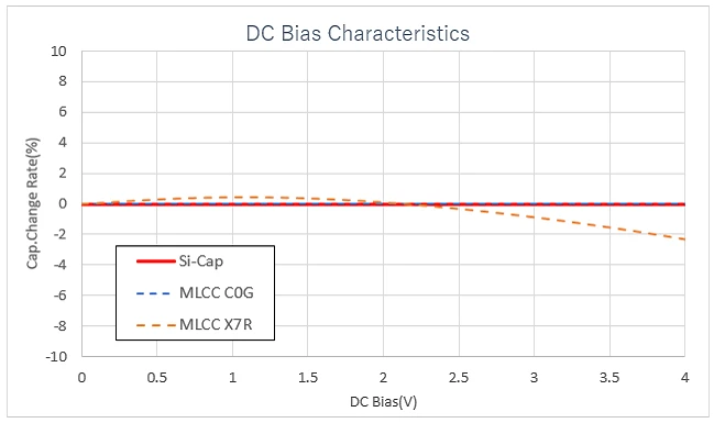
DC Bias Characteristics
The capacitance of silicon capacitors remains virtually unchanged even when voltage is applied, ensuring stable capacitance.
In contrast, although MLCCs feature similar characteristics to silicon capacitors in terms of temperature compensation, for high dielectric constant types the capacitance decreases significantly with applied voltage.
Therefore, when using high dielectric constant MLCCs, it is necessary to take into account this decrease in capacitance due to applied voltage in designs.
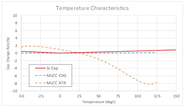
Temperature Characteristics
The capacitance of silicon capacitors remains largely unchanged even with changes in temperature, ensuring stable capacitance.
However, although MLCCs feature similar characteristics to silicon capacitors with respect to temperature compensation, the capacitance of high dielectric constant types changes significantly with temperature.
So when adopting high dielectric constant MLCCs, it is important to consider the change in capacitance due to temperature.
Silicon capacitors also have a wider operating temperature range than general MLCCs, providing stable capacitance even at higher temperatures.
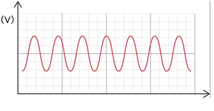
Ringing Noise
Ringing noise is often discovered during final product evaluation, requiring prompt action before the set is sold, as it can cause significant damage.
However, as silicon capacitors do not resonate themselves, there is no need to worry about noise.
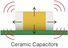
Because ceramic capacitors use piezoelectric elements, voltage fluctuations can cause the capacitor to vibrate in various directions, leading to ringing noise due to resonance of the capacitor itself and base substrate.
An effective measure is to switch to silicon capacitors
Silicon capacitors have no piezoelectric properties
Therefore, there is no ringing problem caused by the product resonating due to voltage fluctuations.
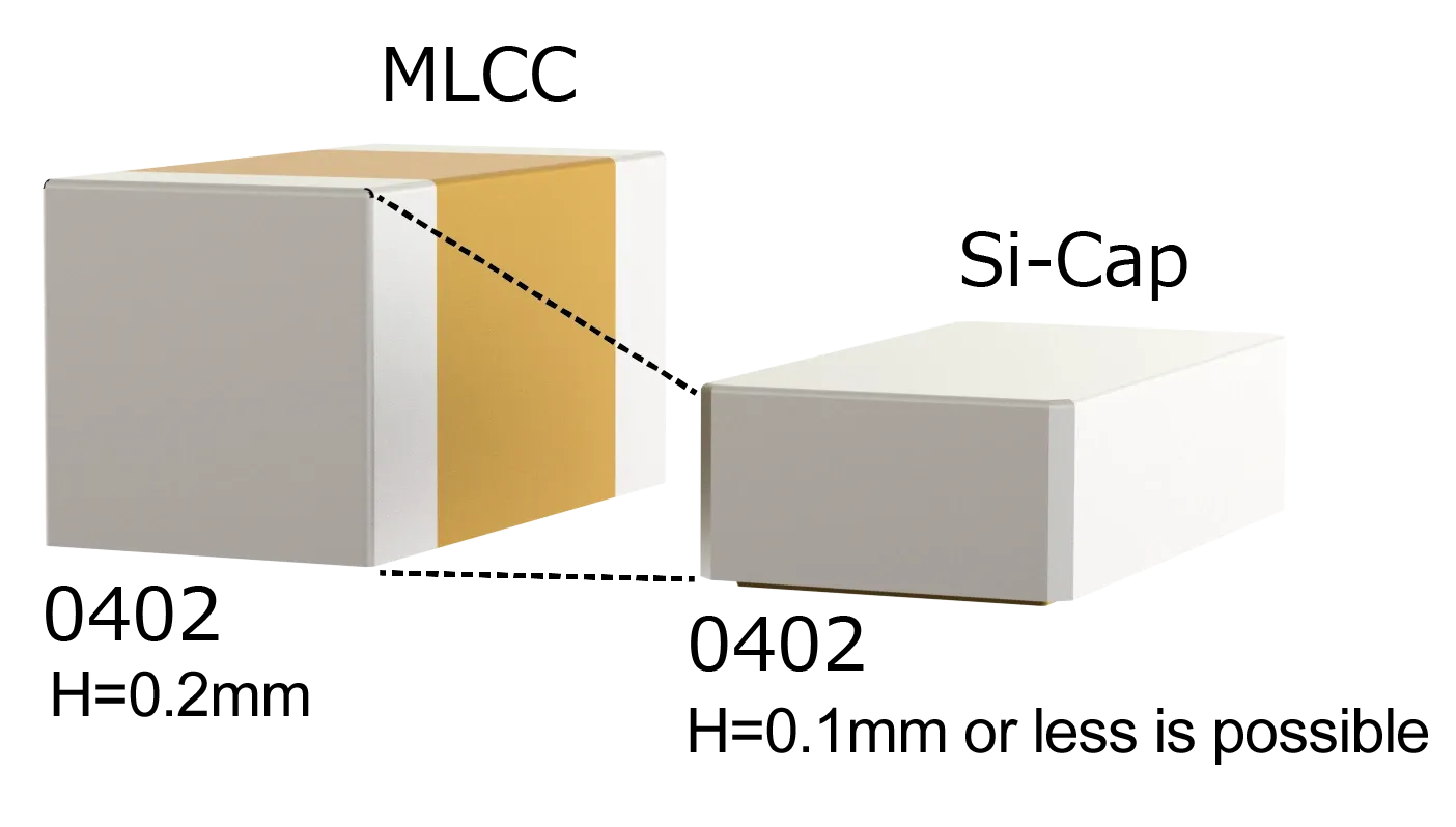
Product Height
Silicon capacitors can achieve a lower profile by forming planar and trench structures using thin-film semiconductor technology.
For example, a product height of 0.1mm or less is possible in the 0402 size (0.4mm x 0.2mm).
On the other hand, MLCCs are comprised of stacked sheets printed with internal electrodes to increase capacitance, making it difficult to reduce height.
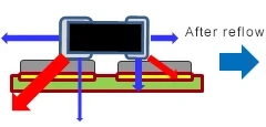
Tombstoning During Mounting (Manhattan Effect / Standing Chip)
The phenomenon whereby the chip stands up during mounting is commonly referred to as the Manhattan effect or tombstoning.
This can be attributed to a variety of factors, including variations in the amount of solder, timing discrepancy in solder melting, and misalignment of the product during mounting.
Utilizing a bottom electrode structure, silicon capacitors lack side electrodes and so are not pulled horizontally, making them less prone to tombstoning during reflow.
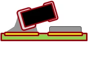
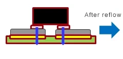
However, MLCCs feature a multi-sided electrode structure that causes the product to be pulled horizontally.
This can lead to tombstoning during reflow due to the above-mentioned reasons.
MLCC : Multi-sided electrode structure
As the sides and bottom are pulled by solder, force is generated in the direction of the red line. In the case of multi-sided electrodes, the difference in contact area between the electrodes and solder can become quite significant.
If the variation is too large, the electrodes will be pulled in the direction of the red line - towards the side with the larger contact area - which can lead to tombstoning.
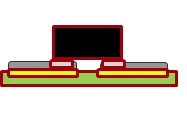
Silicon capacitor : Bottom electrode structure
Since there are no electrodes on the sides, force only acts in the directly below the board.
The bottom electrode design reduces the likelihood of tombstoning.
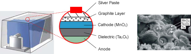
What is a Tantalum Capacitor?
Tantalum is a metal, whose name is derived from Tantalus, an anti hero from Greek mythology. Generally, surface mount tantalum capacitors are constructed by forming electrodes at both ends of the tantalum element using a lead frame, then sealing the structure with mold resin.