Rohm Breadcrumb

op_what1(What are opamps and comparators?)
Oprational Amplifier
<What are Opamps and Comparators?>
What are Opamps?
Opamps (operational amplifiers) are differential amplifiers that amplify the differential voltage between the positive(+)/ negative(-) input pins and are characterized by high input resistance, low output resistance, and high open gain (open loop gain).
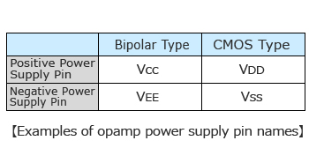
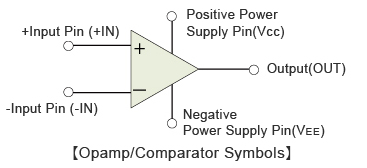
Each circuit consists of 5 terminals: Positive Power Supply, Negative Power Supply, + Input, - Input, and Output.
*In general the names for the power supply, input, and output pins are not standardized
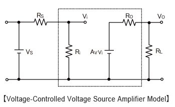
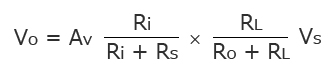
High input resistance (impedance) and low output resistance are required by opamps. In the figure below (Voltage-Controlled Voltage Source Amplifier Model), the relationship between input voltage and the output voltage is expressed by the formula that follows:
To better understand the diagram and formula above:
Vs :Input Signal Source
Rs : Signal Source Output Resistance
Ri : Input Resistance
Ro :Output Resistance
RL : Load Resistance
Av :Gain
The signal voltageVsis divided by the voltage divider based on the signal source resistanceRsand opamp input resistanceRi, with the attenuated signal input into the opamp.
However, when Ri is sufficiently large compared with Rs (Ri=∞), the first term of the equation can be approximated to 1, and viewed as Vs=Vi.
Regarding the second term, the amplified input voltage AvVi is divided and output based on the opamp output resistance Ro and load resistance RL.
At this time, when Ro is sufficiently smaller than RL (Ro=0), the second term can be approximated to 1 and you will see that the signal can be output without attenuation.
This type of opamp is referred to as an ideal opamp. Normal opamps are configured to be as close to the ideal opamp as possible, with high input resistance and low output resistance.

Therefore, it is beneficial for an opamp to have a high amplification factor.
The reason can be explained by the 'Voltage Follower Circuit'.
A voltage follower circuit is one where the input and output voltages are equal. It is primarily used as a voltage buffer, with high input resistance and low output resistance, and Vs=VOUT.
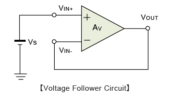
Opamps amplify the differential voltage based on the opamp's amplification factor, with the output voltage expressed as follows.
Therefore,
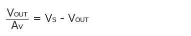
When the open gain Av of the opamp is sufficiently large, the left-hand side can be approximated to 0, and Vs=VOUT.
If the gain is low, the left-hand side of the equation cannot be approximated to 0 and an error will occur at the output voltage.
To achieve high open gain, the output voltage error should be as low as possible based on this gain.
Another way of looking at this is that minimizing the potential difference between the inverting (-) and non-inverting (+) inputs will increase open gain. This means that the larger the open gain gets, the relationship VIN+=VIN- exists. This relationship, where the +Input and -Input pins are virtually equal, is referred to as a virtual short or imaginary short (or imaginary/virtual ground).
Please note that this relationship exists when configuring and utilizing negative feedback circuits and designing application circuits using virtual ground characteristics.
What are Comparators?
Comparators feature the same pin configuration as opamps: + Input, - Input, Positive Supply, Negative Supply, and Output pins. However, with comparators either one of the input pins is used as a reference pin (with a fixed voltage), and the difference in voltage between this reference value and the voltage supplied at the other input pin is amplified, resulting in a High or Low output.
+Input Pin Potential > -Input Pin Potential = Output High
-Input Pin Potential > +Input Pin Potential = Output Low
The primary difference between opamps and comparators is the presence/absence of phase compensation capacitance. Opamps require phase compensation capacitance to prevent internal oscillation, especially when configuring negative feedback circuits.
In contrast, comparators (which are not used to configure negative feedback circuits) do not incorporate internal phase compensation capacitance. As a result, because the response time between the input and output will be limited (due to phase compensation capacitance), comparators generally provide better response vs opamps.
In other words, when using opamps as comparators, responsiveness will be much worse due to the phase compensation capacitance included in opamps. Therefore, caution is recommended when replacing comparators with opamps.
ROHM offers Opamps and Comparators of all types, such as bipolar, CMOS, ground sense , dual supply, low noise,and input/output full swing, to meet a variety of needs.
electronics_tips_menu