Rohm Breadcrumb

D/A Converter Basic Configuration 1 _Decoder Method(da_what5)
DAC <Basic D/A Converter Configurations>
Numerous configurations exist for DAC (D/A converter). We cover the basic configurations below.
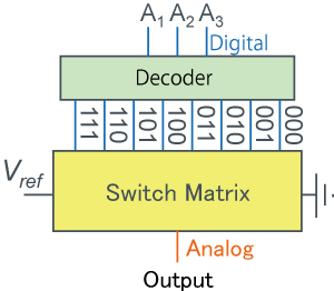
Decoder Method
A decoder is a method that converts a digital signal and then passes it on to another circuit.
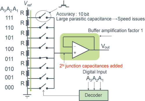
Resistance Voltage Divider Type D/A Converter
In its simplest form, a D/A converter is referred to as a resistance string.
In the 3bit (resolution) D/A converter shown below, voltage is divided via resistors and selected at one node using switches.
However, although sufficiently high-speed operation can be achieved by reducing the resistance values and using a high-speed downstream buffer amp, operating speed is reduced at high resolutions due to parasitic capacitance of the switch.
Advantages include superior linearity and, in principle, guaranteed monotonicity.
>The main disadvantage is exponentially increased circuit scale depending on the resolution.
8 resistors and a switch are needed for 3bit operation, 16 resistors and switch for 4bit, 1024 resistors and a switch for 10bit, etc.
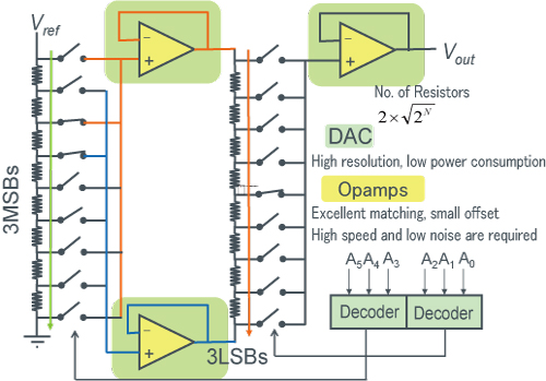
Stage Resistor Voltage Divider Type D/A Converter
This type of resistor voltage divider D/A converter features a 2-stage configuration.
In the 1st stage (left) of the 6bit D/A converter shown below, we select both ends of one resistor between Vref and GND (the third resistor from the top on the left side).
In the 2nd stage (right) the voltage is further divided to obtain higher resolution.
A primary advantage over single-stage configurations is that by restricting circuit scalability the number of required resistors and switches even for a 6bit D/A converter can be limited to 16/18 units (in the case of a resistor voltage divider method, 64 units are required regardless).
Since 2 more amps are needed for each additional stage, considerations must be made when selecting the appropriate method based on the number of resistors/switches.
One disadvantage is that the problems associated with conventional D/A converters are exacerbated.
For example, regarding speed, there will be a delay due to the 2 amps.
And with respect to output voltage accuracy, there may be offset caused by the 2nd stage amps.
Binary Method
A circuit that receives and processes unconverted digital signals is referred to as a binary system.
Binary Method (Using Resistors)
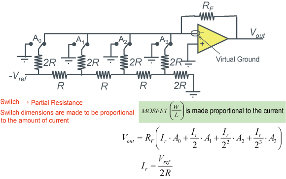
Binary systems provide weighted data to the circuit configuration, as shown below in the representative example of an R-2R ladder circuit.
R-2R ladder circuits appear as parallel connections of resistance values 2R from any node, resulting in half the current per node.
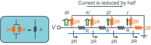
R-2R ladder D/A converter example
The following diagram shows an R-2R D/A converter with 4bit resolution.
This enables the creation of smaller D/A converters with up to 10 bit resolution (required resistors include 3N for Nbit D/A converter, and neither a decoder nor large switches are needed), and when combined with other methods resolutions up to 14bits are possible.
However, one drawback is that due to the high relative accuracy required for the resistors, both switch (MOSFET-sized) and layout optimizations (the R and 2R pair are important, and the MSB = A0 resistance must be accurately created) are required to achieve high precision operation.
Binary Method (Using Capacitors)
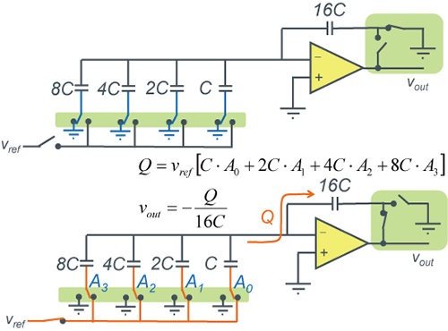
The conceptual diagrams below illustrate the concept of a D/A converter using capacitors.
This D/A converter requires use while switching.

D/A Converter using 2NC capacitors example
A 4bit D/A Converter utilizing capacitors is shown in the below diagram. Whichever switch (A0 to A3) falls on the Vref side will make it possible to obtain a different Vout voltage. When both switches on the amp at the right are turned on at the same time, the relationship with charge storage is lost, making it necessary to prevent ON-time overlap using clock signals.
The advantage of this method is that the high relative accuracy of capacitors makes high precision operation possible, plus DC current is not generated in the capacitors, enabling low current consumption at low frequencies since only the amp current flows.
The disadvantage is that higher speeds are not possible due to capacitor charging/ discharging, and refresh operation is required at low speeds in order to compensate for leakage current.
D/A Converter example utilizing 2NC capacitors(with refresh control)
4bit DAC with refresh control using capacitors
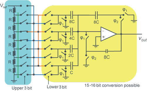
Binary method (Using resistors and capacitors)
A 6bit resolution mixed type D/A converter can be configured using a 3bit resistor string D/A converter (left) and 3bit capacitor D/A converter.
Voltage across the resistors of the upper bits are weighted and compensated based on the data from the lower section.
The ability to obtain high resolutions provides a distinct advantage.
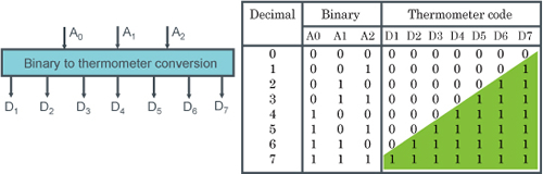
Thermometer Code Method
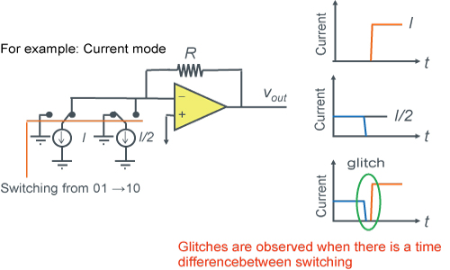
At the moment data is switched there may be a very different output voltage, possibly causing noise to be generated at the output analog signal. This noise can be referred to as a glitch. As one workaround for these types of glitches, the thermometer code method is often used.
Thermometer codes are the representation of numbers based on how many '1s' are present. However, although glitches can be reduced, the size of decoders for binary to thermometer code can increase in scale exponentially based on resolution.
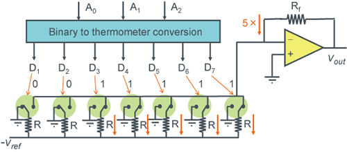
Thermometer Code (Resistance Mode) D/A Converter Example
3bit DAC using thermometer codes.
Natural glitches do not occur.
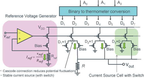
Thermometer Code (Current Mode) D/A Converter Example
A current mode D/A Converter determines the output voltage Vo by pulling current from a number of cells.
The figure below shows an 8x8 configuration (64 gradation) = 6bit resolution
By simply increasing the pink section, current pulled from R rises, reducing Vout.
Thermometer code control prevents glitches from occurring at Vout.
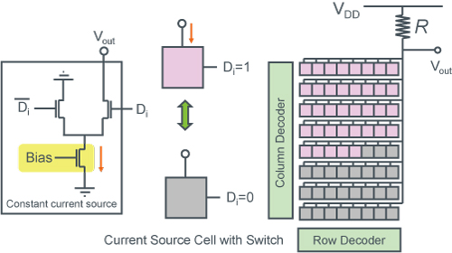
In the above diagram of a current type D/A converter, up and down are reversed.
Cascode current sources are less affected by output voltage, achieving high accuracy.
As a result, the output voltage range is reduced.
electronics_tips_menu